Download
1 / 22
230 likes | 491 Views
NONDESTRUCTIVE TESTING USING AIR-BORNE ULTRASOUND. What is NDT ? Testing of materials, without destroying them. Using ultrasound (frequency in the range of 20khz to 20 MHz). CONTENTS. Introduction Air-coupled ultrasonic NDT: general considerations Air-coupled ultrasonic instrumentation

E N D
What is NDT ? • Testing of materials, without destroying them. • Using ultrasound (frequency in the range of 20khz to 20 MHz).
CONTENTS • Introduction • Air-coupled ultrasonic NDT: general considerations • Air-coupled ultrasonic instrumentation • Laboratory testing • Field application • Discussion and conclusion • References
INTRODUCTION • This paper presents the fundamentals of making air-borne ultrasonic measurement, and point out special considerations unique to propagating ultrasound in air and through solids. • Piezoelectric, air-coupled Transducers were developed for the generation and reception of air-borne ultrasound, thus enabling the non-contact, non-contaminating inspection of composite laminates and honeycomb structures widely used in the aerospace industry.
Air-coupled ultrasonic NDT: general considerations • Main obstacle in using air-coupled ultrasound for inspecting solids is the extremely inefficient energy transfer from air to the solid. • Calculation of the transmission of an air-coupled ultrasonic pulse or toneburst through a plate takes into account the frequency spectrum of the signal.
fig. 1. Transmitted air-coupled ultrasound amplitude versus thickness of carbon composite using a 200 kHz center frequency transducer.
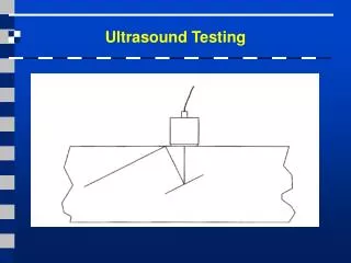
The thickness dependence of transmission shown in Fig. 1 is important for the quantitative interpretation of air-coupled ultrasonic test results of structures. • Majority of nondestructive testing using air-coupled ultrasound is carried out in the transmission mode where two-sided access is required. • One sided testing in the pitch-catch mode is possible, provided the receiving transducer is shielded from the strong specular reflection and scattering of the transmitted beam at the surface. • With oblique incidence, air-coupled transducers can also be used in the generation of plate or Lamb waves, which can then be used in the scan of plate structures for detecting flaws, damage, and material anomalies.
Air-coupled ultrasonic instrumentation • Piezoceramic type air-coupled ultrasonic transducers are commercially available over the 50 kHz to 1 MHz frequency range. Some vendors provide the associated electronics (pulsar, receiver, control, and display) optimized for their transducers whereas others provide transducers that can be driven with a variety of voltage sources. • Recently a group has driven a pair of “GMP” transducers from Ultran with a portable ultrasonic flaw detector and was able to obtain reasonably strong echoes in a 2-in. thick carbon composite solid laminate with the aid of a battery-powered low-noise preamplifier, as shown in Fig. 2.
fig.2. Driving air-coupled ultrasonic transducer with portable flaw detector for inspecting thick carbon composite laminate.
Output of Laboratory testing fig.3. Manual (left) and mechanized (right) C-scans of defects in a honeycomb sandwich panel using 120 kHz air-coupled transducers. • Detection and imaging of flaws and damage in composite laminates using air-coupled ultrasound.
The results in Fig. 3 show that manual C-scans of defects in honeycomb sandwiches revealed almost equally accurate flaw size and shape as that in mechanized scans. • Honeycomb sandwich structures are ubiquitous on aircraft. They account for most of the flight control surfaces such as spoilers, flaps, rudders, and trailing edge. Since these components do afford two-sided access, air-coupled ultrasonic inspection is appropriate. • Defects such as foreign object inclusion, disbond, delamination, and damages such as honeycomb core crush or buckling due to impact or static overload can be imaged with air-coupled ultrasonic transmission. The defects and damage appear as regions of reduced transmission amplitude.
Fig. 4 shows an image of a glass polyester panel with 1/2 in. thick Divinycell foam core. fig.4. Air-coupled ultrasonic transmission scan image of glass polyester panel containing slit Divinycell foam core and engineered defects.
Field application • In aerospace applications, portable ultrasonic flaw detectors are used on the aircraft in the contact mode with coupling gel applied under the transducer. Such “A scan” inspection does not have the benefits of an image of the inspect data. Squirter type scanning systems cannot be used in a maintenance hangar, but several water-coupled ultrasonic scanning systems that used limited wetting have been developed. • In an airline hangar environment, the inspection results can be presented and saved as a C-scan image. In this work, we have developed two portable manual scanners for conducting on aircraft, air-coupled ultrasonic C-scans in the field.
The first system combines a QMI air-coupled ultrasonic instrument with a magnetic encoding device known as the “Flock of Birds” (FOB), as shown in Fig. 5. The piezoceramic transmitting and receiving transducers, driven by the QMI Air scan pulse/receiver, are mounted on a “yoke” for transmission inspection. • The FOB system consists of a transmitter and a receiver. • Using the spatial data and the air-coupled transmission amplitude, a C-scan is produced.
fig.5.Block diagram of a manual C-scan system for air-coupled ultrasonic inspection using a magnetic “Flock of Birds” (FOB) position encoder.
fig.6. Scanning the damage of a helicopter rotor blade using air-coupled ultrasonic transmission and FOB encoding.
Fig. 6 shows the yoke being applied to a rotor blade of a helicopter that had suffered some damage. The scan image clearly shows two impact-induced damages running in the circumferential direction. The image was produced using a software for better definition of the defects and for a faster scan overall.
More recently, a more portable air-coupled ultrasonic C-scan system was developed for field use. A pair of Ultran GMP transducers driven by a flaw detector, as shown earlier in Fig. 2, is mounted on a transducer yoke. The position encoding is achieved by adopting the Mimio system , a commercially available device designed for capturing handwritings and drawings on a white-board or flipchart. As with the FOB system, the NDT data in the form of an amplitude of the transmitted ultrasonic pulse within a time gate are merged with the position data from the Mimio in the generation of the C-scan image.
fig.7. Manual air-coupled ultrasonic C-scan of a rudder skin panel using GMP air-coupled transducers, a portable flaw detector, and the Mimio position encoder • Fig. 7 shows the manual inspection of a rudder skin panel with the new system. The image on the screen in the photograph shows two regions of skin-to-core disbond at the edge of the panel. Since the ultrasonic flaw detector is battery powered and the Mimio is powered from a laptop PC, the new system requires no AC power supply and can be conveniently applied on an aircraft in the field. The system is currently undergoing field tests in aircraft hangars.
Discussion and Conclusions • Composite and aluminum honeycomb structures and components on aircraft that require inspection can be quite complex and may contain substructures, internal reinforcement, and benign design features. • In the past, ultrasonic scanning has been hampered by the problem of the couplant and the complexity, weight, and cost of motorized scan frames. With air-coupled ultrasound, the couplant problem is totally avoided. • With novel use of simple and inexpensive devices designed for other purposes but having position encoding capability, manual C-scans can be practically implemented in the field. The combination of efficient air-coupled transducers and simple manual scanners has created a new simple and cost-effective inspection.
References • [1] D.K. Hsu, D.J. Barnard, J.J. Peters, V.Dayal,Development of nondestructive inspection methods for composite repair, in: D.O.Thompson, D.E. Chimenti (Eds.), Rev. Prog. Quantitative NDE, vol.22, AIP, 2003, pp. 1019–1025. • [2] J.J. Peters, D.J. Barnard, D.K. Hsu, Development of a fieldable aircoupled ultrasonic inspection system’’, in: D.O. Thompson, D.E.Chimenti (Eds.), Rev. Prog. Quantitative NDE, vol. 23, AIP, 2004,pp. 1368–1375. • [3] D.J. Barnard, J.J. Peters, D.K. Hsu, Towards a generic manual scanner for nondestructive inspection, in: D.O. Thompson, D.E.Chimenti (Eds.), Rev. Prog. Quantitative NDE, vol. 24, AIP, 2005,pp. 1669–1676. • [4] J. Krautkramer, H. Krautkramer, Ultrasonic Testing of Materials,fourth ed., Springer-Verlag, Berlin Heidelberg, 1990, p. 19. • [5] S.D. Holland, D.E. Chimenti, High contrast air-coupled acoustic imaging with zero group velocity lamb modes, Ultrasonics 42 (2004)957–960. • [6] S. Matsubara, T. Nagai, T. Yoshiara, M. Shirai, H. Miyamoto, Aircoupled ultrasonic inspection method for CFRPAdvances in Nondestructive Evaluation, Part 3, Trans Tech. Pub, Switzerland, 2004, pp. 1884–1891. • [7] QMI, Inc., Huntington Beach, California, USA. Available from: <http://www.qmi-inc.com>. • [8] The Ultran Group, State College, Pennsylvania, USA. Available from: <info@ultrangroup.com>. • [9] J.O. Trycek, H. Loertscher, Ultrasonic air-coupled inspection of advanced materials, 44th International SAMPE Symposium and Exhibition, Long Beach, CA, 1999. • [10] D.W. Schindel, D.A. Hutchins, W.A. Grandia, Capacitive and piezoelectric air-coupled transducers for resonant ultrasonic inspection, Ultrasonics 34 (1996) 621–627. • [11] D.W. Schindel, Air-coupled ultrasonic measurements of adhesively bonded multi-layer structures, Ultrasonics 37 (1998) 185–200. • [12] V. Kommareddy, Air-coupled ultrasonic measurement in composites, in: D.O. Thompson, D.E. Chimenti (Eds.), Rev. Prog. Quantitative NDE, vol. 23, AIP, 2004, pp. 859–866. • [13] J.J. Peters, V. Dayal, D.J. Barnard, D.K. Hsu, Resonant transmission of air-coupled ultrasound through metallic inserts in honeycomb sandwich structures, in: D.O. Thompson, D.E. Chimenti (Eds.), Rev. of Prog. In Quantitative NDE, vol. 24, Amer. Inst. Phys., Melville,NY, 2005, pp. 1026–1032. • [14] D.D. Palmer and Nancy Wood, Mobile Automated Scanner System (MAUS), Final Report to Air Force Research Laboratory, AFRLML-WP-TR-1999-4104, 1999. • [15] D.J. Barnard, D.K. Hsu, Development and testing of the dripless bubbler ultrasonic scanner, in: D.O. Thompson, D.E. Chimenti (Eds.), Rev. of Prog. in Quantitative NDE, vol. 16, Plenum Press, New York, 1997, pp. 2069–2076. • [16] Mimio by Virtual Ink, Inc. Available from: <www.mimio.com>. e1024 D.K. Hsu / Ultrasonics 44 (2006) e1019–e1024.