Download
1 / 54
540 likes | 664 Views
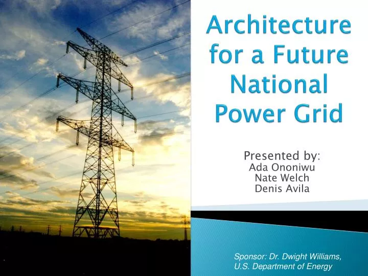
Architecture for a Future National Power Grid. Presented by: Ada Ononiwu Nate Welch Denis Avila. Sponsor: Dr. Dwight Williams, U.S. Department of Energy. Agenda. Background Problem Mission Statement Strategy and Approach Stakeholder Identification Requirements Concept of Operations

E N D
Architecture for a Future National Power Grid Presented by: Ada Ononiwu Nate Welch Denis Avila Sponsor: Dr. Dwight Williams, U.S. Department of Energy
Agenda • Background • Problem • Mission Statement • Strategy and Approach • Stakeholder Identification • Requirements • Concept of Operations • Technology Strategy • System Architecture • Business Case • Conclusion and Recommendations
Agenda • Background • Problem • Mission Statement • Strategy and Approach • Stakeholder Identification • Requirements • Concept of Operations • Technology Strategy • System Architecture • Business Case • Conclusion and Recommendations
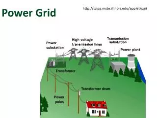
Background • U.S. Power Grid covers the 48 contiguous states (and parts of Canada and Mexico). • The grid is divided into three interconnected systems • Eastern Interconnected System • Western Interconnected System • Texas Interconnected System • Predominantly operate independently, but also are redundantly connected by direct-current (DC) lines.
Agenda • Background • Problem • Mission Statement • Strategy and Approach • Stakeholder Identification • Requirements • Concept of Operations • Technology Strategy • System Architecture • Business Case • Conclusion and Recommendations
Problem • The current U.S. power grid is aging, inefficient, congested, and is vulnerable to power outages and power disturbances • With the consumer power demand expected to increase by 26% over the next 20 years and exceed power generation by 2024, there is a need to upgrade the current U.S. power grid
Agenda • Background • Problem • Mission Statement • Strategy and Approach • Stakeholder Identification • Requirements • Concept of Operations • Technology Strategy • System Architecture • Business Case • Conclusion and Recommendations
Mission Statement • The project development team will serve as an energy consulting firm to the DOE, where an architectural solution will be sought to support the ongoing efforts to improve the U.S. power grid. • The objective of the development team is to implement a systems engineering methodology that will result in a completed, proof-of-concept future power grid architecture. • The project report will serve as an informal submission that provides an alternative conceptual approach to addressing the many current grid problems. • Deliverables will include: • Documentation of the methods used to develop multiple grid architectures • An evaluation of each architecture • A Business Case that will recommend a specific architecture
Agenda • Background • Problem • Mission Statement • Strategy and Approach • Stakeholder Identification • Requirements • Concept of Operations • Technology Strategy • System Architecture • Business Case • Conclusion and Recommendations
Strategy and Approach (2 of 2) • Department of Defense Architecture Framework (DoDAF) was selected for the design and development of the Future National Power Grid Architecture • An architecture modeling tool, MagicDraw, was implemented to design and model DoDAF Operational View (OV) and Systems View (SV) products
Agenda • Background • Problem • Mission Statement • Strategy and Approach • Stakeholder Identification • Requirements • Concept of Operations • Technology Strategy • System Architecture • Business Case • Conclusion and Recommendations
Stakeholder Identification (1of 3) • By using the stakeholders involved in the development of the DOE’s “Grid 2030 Vision” and the “Modern Grid Strategy”, the pertinent stakeholders that would have some influence on the mission of this project were identified
Stakeholder Identification (2of 3) • Used stakeholder analysis tool by Mind Tools to determine which stakeholders had the greatest influence or impact to the project. • The resulting value map allows the project development team to trace the origin of each of the system requirements
Stakeholder Identification (3of 3) • The Quality Function Deployment (QFD) model was used to transform stakeholder needs into the power grid quality characteristics (or functional requirements) • The final results of the QFD analysis defined which functional requirements are most important based on their relative weights • The top five functional requirements is what this project will focus on, at a minimum
Agenda • Background • Problem • Mission Statement • Strategy and Approach • Stakeholder Identification • Requirements • Concept of Operations • Technology Strategy • System Architecture • Business Case • Conclusion and Recommendations
Requirements (1 of 2) • Based on the analysis from the QFD model, the following functional requirements (in priority order) will be taken into consideration when designing a future architecture power grid: • Minimize system costs • Increase power quality • Reduce power loss • Tolerant to security threats and attacks • Accommodate energy storage options • Decrease system peak demand • Increase reliability • Decrease transmission line congestion • Decrease system restoration time • Decrease need for new power stations and transmission lines • Incorporate interoperability government standards & policies • Increase environmental benefits • Decrease time to develop system Intent is to address these requirements at a minimum
Requirements (2 of 2) • The following system attributes would be taken into consideration: • Extensibility –The power grid architecture will allow for the modification of existing functions and inclusion of new functions • Feasibility – The power grid architecture will be of a viable design to realistically implement • Reliability – The power grid architecture will eliminate or minimize power outages. Based on the mean time before failure (MTBF) (or number of steps to balance the nodes), the grid architecture that has the lowest MTBF (or number of steps) will mostly likely be selected. • Flexibility – The power grid architecture will adapt when external changes occur and must be flexible to meet future demands and new technologies • Scalability –The power grid architecture will meet consumer demands during peak and off-peak seasons • Interoperability – Existing power grid components will be able to operate with the proposed power grid architecture • The pertinent power grid standards, codes, and regulations are also taken into consideration (e.g., OSHA, IEEE, etc.)
Agenda • Background • Problem • Mission Statement • Strategy and Approach • Stakeholder Identification • Requirements • Concept of Operations • Technology Strategy • System Architecture • Business Case • Conclusion and Recommendations
Concept of Operations (1of 3) • Project Scope • The U.S. power grid has three primary operations—electricity generation, electric power transmission, and electricity distribution • This project will focus solely on two of the power grid operations, generation (the implementation of) and top-level transmission
Concept of Operations (2of 3) • From the perspective of the project scope, the OV-1 displays the high-level graphical description of the operational concept.
Concept of Operations (3of 3) • Use case diagrams were developed to explore the operational activities necessary to address the problem and meet requirements • Two use cases have been developed: • Generate Power – provides constant power to end user • Regulate Power – regulates power demand on extra high voltage grid with a successful end result that does not interrupt the grid’s power with the addition and removal of end users Generate Power Use Case Regulate Power Use Case
Agenda • Background • Problem • Mission Statement • Strategy and Approach • Stakeholder Identification • Requirements • Concept of Operations • Technology Strategy • System Architecture • Business Case • Conclusion and Recommendations
Technology Strategy (1 of 2) • Critical to the Future National Power Grid architecture are the properties of extensibility and flexibility • The developed architecture must adhere to the ideal of technological acceptance as new energy technologies are developed and implemented • The project development team envisions their architecture to provide such a compliant capability
Agenda • Background • Problem • Mission Statement • Strategy and Approach • Stakeholder Identification • Requirements • Concept of Operations • Technology Strategy • System Architecture • Business Case • Conclusion and Recommendations
System Architecture (1 of 7) • Functional Decomposition
System Architecture (2 of 7) • The following key characteristics were vital to the design of the proposed power grid architecture: • Extra High Voltage (EHV) Transmission Line Specification • Nodal Connectivity • Auto-Regulation • Colored Petri Nets (CPN) were developed to aid in the conceptual development and analysis of multiple EHV power grids: • Energy Source Transition • Energy Distribution • Power source to consumer transmission • Geographically dispersed • Congestion alleviation
System Architecture (3 of 7) • Power source to consumer transmission: Based on the current production and consumption of each state, main power flow was determined within the country. This layout attempts to broaden those paths. While the location of power production will change over time, the current layout is assumed to serve as a guide.
System Architecture (4 of 7) • Geographically dispersed: This model attempts to provide broad area coverage throughout the country to facilitate its interconnection with the HV grid.
System Architecture (5 of 7) • Congestion alleviation: This model focuses of alleviating current power congestions. While this configuration will continue to provide the advantages of the prior models, it will also provide quicker relief to the current power distribution problems. Future Congestion Current Congestion
System Architecture (6 of 7) • Run CPN Simulation
System Architecture (7 of 7) • CPN Results:
Agenda • Background • Problem • Mission Statement • Strategy and Approach • Stakeholder Identification • Requirements • Concept of Operations • Technology Strategy • System Architecture • Business Case • Conclusion and Recommendations
Business Case (1 of 4) • The business case analysis focused on the 3 physical layout lifecycle costs • Lifecycle costs were based upon top-level physical components of the power grid architecture, EHV transmission lines and substations • The following cost factors were considered: • Engineering and construction costs of implementing EHV transmission lines over different environmental terrain (e.g., mountains), • Integration of EHV substations, and • Operations and Maintenance (O&M) costs
Business Case (2 of 4) • Cost Methodology • Superimposed each physical layout of the grid architecture and a U.S. terrain map* • Identified the nearest city at each power grid node • Using a distance calculator tool, all transmission line distances were determined • Using various online sources, commercial costs for transmission lines and substations were: • Transmission line engineering and construction costs (cost per mile): $2.5M • Transmission line O&M costs** (cost per mile): $4K • Substation engineering and construction costs (cost per unit): $32.7M • Substation O&M costs** (cost per unit): $250K * Assumed 1.3X cost factor for mountain terrain in western U.S. states ** Assumed 50 year lifespan
Business Case (3 of 4) • Lifecycle Cost Results Power Source to Consumer had the least expensive lifecycle cost
Business Case (4 of 4) • Analysis of Alternatives: • Although minimizing total system cost was defined as the top priority functional requirement, the project development team strived to select the architecture layout which balanced both performance and cost • Layouts that required more simulation steps to self-balance were increasingly expensive • Increased redundancy promotes greater reliability; however, at the expense of efficiency
Agenda • Background • Problem • Mission Statement • Strategy and Approach • Stakeholder Identification • Requirements • Concept of Operations • Technology Strategy • System Architecture • Business Case • Conclusion and Recommendations
Conclusion and Recommendations • Successfully developed 3 future architecture grids • Recommendation is to implement “Power source to consumer” layout to the DOE • Due to the limited time and scope of this project, all aspects of the power grid architecture could not be explored and analyzed. Future research should be considered for the purposes of expanding the grid architecture in the following areas: • EHV substation placement using more detailed statistics; • A detailed cost analysis assuming more realistic industry standards (i.e. underground/overhead transmission lines, a mix of tubular steel pole transmissions and lattice towers, etc.); • Architecture expansion at the regional/local level; and • Simulation of power outages and point failures for grid analysis. • For more information, please visit our project website at: http://mason.gmu.edu/~davila/index.htm Recommend Power Source to Consumer architecture to DOE
Special Thanks • Project Sponsor • Dr. Dwight Williams, Senior Science Advisor, U.S. Department of Energy • SEOR Faculty