Download

1 / 30
300 likes | 611 Views
System Engineering. CIS 375 Bruce R. Maxim UM-Dearborn. Computer System Elements. Software. Hardware. People. Databases. Documentation. Procedures (for humans, not code). System Engineering. Don't take a "software-centric" view of the system.

E N D
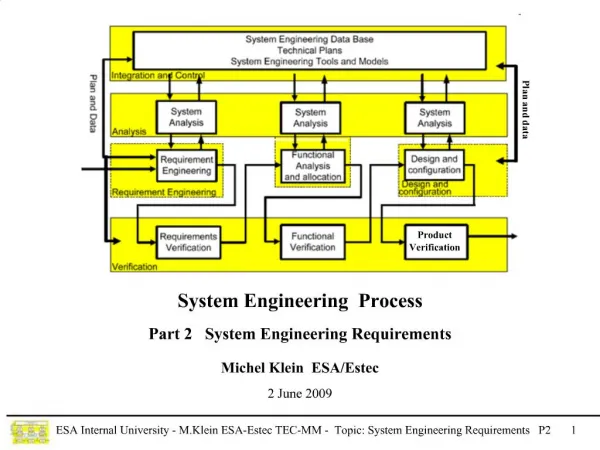
System Engineering CIS 375 Bruce R. Maxim UM-Dearborn
Computer System Elements • Software. • Hardware. • People. • Databases. • Documentation. • Procedures (for humans, not code).
System Engineering • Don't take a "software-centric" view of the system. • Consider all system elements before focusing on software. • System engineering begins with a clear understanding of the "world view" and progressively narrows until technical detail is understood. • Complex systems are actually a hierarchies of subsystems.
System Engineering Hierarchy • World view • Domain view • Element view • Detailed view
Project Engineering Hierarchy • Requirements engineering • world view • Component engineering • domain view • Analysis and Design modeling • element view (software engineers) • Construction and Integration • detailed view (software engineers)
Business Process Engineering Hierarchy • Information Strategy Planning • world view • Business Area Analysis • domain view • Business System Design • element view (software engineers) • Construction and Integration • detailed view (software engineers)
Business Process Engineering Architectures • Data architecture • provides framework for information needs of a business or business function • Applications architecture • system elements that transform objects within the data architecture for some business purpose • Technology infrastructure • provides foundation for the data and application architectures
Computer Systems Engineering • Software Engineering • Hardware Engineering • Human Engineering
Computer System Analysis Tasks -1 • Transform customer defined goals and constraints into system representation describing: • Function. • Performance. • Interfaces. • Design constraints. • Information structures.
Computer System Analysis Tasks -2 • Bound the system and select the configuration using: • Project schedule and costs. • Business considerations. • Technical analysis. • Manufacturing evaluations. • Human issues. • Environmental interface. • Legal considerations.
Human Engineering • Activity analysis • watch the people you’re supporting • Semantic analysis and design • what and why they do things • Syntactic and lexical design • hw & sw implementation (e.g key strokes) • User environment design • physical facilities and HCI stuff
Requirements Engineering - 1 • Requirements Elicitation • find out from customer what the product objectives are what is to be done how the product fits into business needs how the product is used on a day to day basis • Requirements Analysis • requirements organized into subsets • relations among requirements identified • requirements reviewed for correctness • requirements prioritized based on customer needs
Requirements Engineering - 2 • Requirements Specification • work product produced describing: function performance development constraints for system • System Modeling • system representation that shows relationships among the system components
Requirements Engineering - 3 • Requirements Validation • examines the specification to ensure requirement quality • make sure work products conform to agreed upon standards • Requirements Management • set of activities that help project team to control and track requirements changes as project proceeds
Traceability Tables • Features traceability table • Source traceability table • Dependency traceability table • Subsystem traceability table • Interface traceability table
System Modeling • Define processes that serve needs of the view under consideration • Represent process behavior and the assumptions on which it is modeled • Explicitly define links between constituents and the links between constituent components that are input to the model • Represent all linkages (including outputs) required to understand the view
System Model Restraining Factors • Assumptions • Simplifications • Limitations • Constraints • Preferences
System Model Template • User interface • Input • Process and control functions • Output • Maintenance and self test
Systems Modeling Process - 1 • System Context Diagram (SCD or ACD) • top level node in system hierarchy used to establish the boundaries for the system being implemented • System Flow Diagram (SFD or AFD) • refinement of the process and control functions from SCD • derived by identifying the major subsystems and lines of information flow
Systems Modeling Process- 2 • Initial SFD is becomes the top level node of a hierarchy of more successively more detailed SFD's • System Specification • developed by writing narrative description for each subsystem and definitions for all data that flow between subsystems
System Simulation • If simulation capability is not available for a reactive system, project risk increases. • Consider using an iterative process model that will allow the delivery and testing of incrementally more complete products.
USER INTERFACE PROCESSING PROCESS AND CONTROL FUNCTIONS INPUT OUTPUT PROCESSING PROCESSING MAINTENANCE AND SELF-TEST • ACD Component Management Engineer Design Component Part Number or Validation Menu Selection Result Table1.CSV Master PN and 3D Model Info Part Number Printer Table2.CSV Analysis (PNA) Tool Master PN and Validation Cross-Ref PN Result Data Error WKConnectors . Message CSV Design Component Part Number Component Management Engineer
AFD Operator Interface View/Print Validation Results Design Component Part Operator Number or Menu Selection Interface subsystem Display GUI Per form Analysis Requested Data Error Data Request Message Application Connectivity Check and Instructions Startup Part Number subsystem Analysis Formatted subsystem Validation Result MS ACCESS MS ACCESS Data Source Design Component Part Printing Formatted Connectivity Number, Master Part Validation subsystem Number, Cross-Ref Part subsystem Result Number and Model Information Report Formatting subsystem Data Table Management Validation Design Component Part subsystem Result Unformatted Number, Master Part PNA Processing Validation Number, Cross-Ref Part Result Number and Model Error Information Error Code Error Code and Control Code Error Code MS ACCESS Error Code Run-time Diagnostics Error Code subsystem Data Acquisition Output Interface Interfaces Diagnostic Interface
Data Processing REPORT 10 TBL_CREATEDWKCONN VALIDATION DATA WKCONNECTORS - UNIQUE PN - USAGE COMPARISON RESULT 1 2 TABLE CRITERIA 9 QUERY CONSTRUCT SUB-TABLES COMPARE DATA 8 3 6 5 TBL_CREATEDT1 7 TABLE1 QUERY RESULT CRITERIA: (1) Do not consider leading zeroes and dashes (2) Consider leading zeroes and dashes TBL_CREATEDT2 4 TABLE2 QUERY RESULT
Main Status PART NUMBER ANALYSIS TOOL Please wait… (Version / Release Date) Data analysis currently in progress. Part Number Quick Check Status Analyze Part Numbers Data analysis finished. View / Print Report Report has been created. Save Report OK (Logo / Branding) Exit Help Output To Part Number Quick Check Select format OK Part Number HTML Cancel Microsoft Excel MS-DOS Text Rich Text format Analyze Close Snapshot format Result Part Number *** belongs to category X (GOOD/NEW/BAD) Comments: (Place Remarks here) OK • Storyboard MULTIPLE PART NUMBER VALIDATION Updated when analysis is finished. PREVIEW REPORT ON SCREEN. SAVE VALIDATION DATA MS ACCESS dialog carries out File Save Process SINGLE PART NUMBER VALIDATION
DFD/CFD Level 0 - Part Number Analysis (PNA) System WKConnectors.XLS Spreadsheet Information CSV File Creation (WKConnectors.CSV) Display Monitor WKConnectors Delimited Text Information Report Results Table1.CSV PART NUMBER ANALYSIS (PNA) Tool File Table1 Delimited Text Information Report Results Table2 Delimited Text Information Report Results Table2.CSV Printer - Command - PN data User
DFD/CFD Level 1 - Part Number Analysis (PNA) Tool WKConnectors Delimited Text information Report Results Validation Results Validate Data Process Report Table1 Delimited Text information Report Results Print / Save Data Report Results Table2 Delimited Text information - Command - PN data
tbl_Classification • DFD/CFD Level 2 - Validate Data Make tbl_createdWKConn WKConnectors Delimited Text information Relevant WKConnector Records Category Reference ID Validation Results - Command - PN data Make WKConn tbl_createdWKConn WKConn field data • Component Remarks • Category ID tbl_createdT1 Analyze/Classify Data T1 Field data Relevant T1 Record(s) Print / Save Data Criteria: - dbs - strCriteria - strOrigPN Criteria: - dbs - strOrigPN Make tbl_createdT1 Table1 Delimited Text information T2 Field data Make tbl_createdT2 tbl_createdT2 Relevant T2 Record(s) Table2 Delimited Text information
DFD/CFD Level 3 - Make tbl_createdT1 Criteria: - dbs - strCriteria - strOrigPN qry_Table1UniquePN Recreate tbl_createdT1 Table1 Delimited Text information Relevant T1 Record(s) Table1 Query Results • DFD/CFD Level 3 - Make tbl_createdT2 Criteria: - dbs - strOrigPN Recreate tbl_createdT2 qry_Table2PrelimUnique Table2 Delimited Text information Table2 Query Results Relevant T2Record(s)