Download
1 / 40
460 likes | 1.02k Views
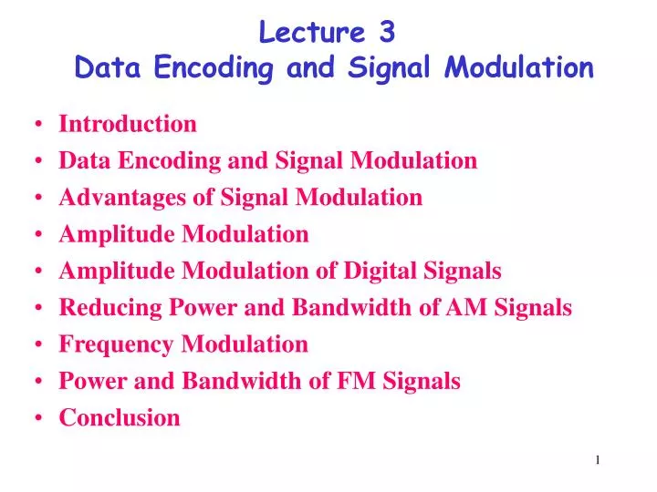
Lecture 3 Data Encoding and Signal Modulation. Introduction Data Encoding and Signal Modulation Advantages of Signal Modulation Amplitude Modulation Amplitude Modulation of Digital Signals Reducing Power and Bandwidth of AM Signals Frequency Modulation

E N D
Lecture 3 Data Encoding and Signal Modulation • Introduction • Data Encoding and Signal Modulation • Advantages of Signal Modulation • Amplitude Modulation • Amplitude Modulation of Digital Signals • Reducing Power and Bandwidth of AM Signals • Frequency Modulation • Power and Bandwidth of FM Signals • Conclusion
Introduction A network and transport layers basic services comprise the end-to-end transport of the bit streams over a set of routers (switches). They are produced using six basic mechanisms: a. Multiplexing b. Switching c. Error control d. flow control e. congestion control f. and resource allocation.
Multiplexing Combines data streams of many such users into one large bandwidth stream for long duration. Users can share communication medium. a. Switch b. Multiplexer/Demultiplexer a. Fully connected networkb. network with shared links.
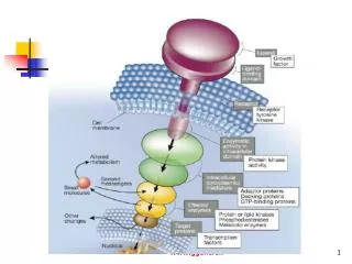
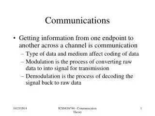
Data Encoding is • the process of preparing data for efficient and accurate transmission. • Because analog data is altered by noise in transmission, the process of analog-to-digital conversion allows more accurate transmission of data. The conversion process will not change the analog data, in conversion the information contained in the analog data will not be destroyed by the conversion process. Once the data is in digital form, it can be encoded as a sequence of voltage levels. Signal Modulation is • the process of encoding a baseband source signal Sm (t) onto a carrier signal. • The carrier waveform is varied in a manner directly related to the baseband signal. The carrier can be a sinusoidal signal or a pulse signal. The result of modulating the carrier signal is called the modulated signal.
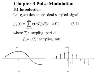
Sampling using PAM. s > 2B
Signal Modulation Sc( t ) = A · cos ( 2 f t+ ) A. Amplitude Modulation (AM), or Amplitude Shift Keying (ASK): The amplitude A of the carrier signal changes in direct proportion to the baseband signal. B. Phase Modulation (PM), or Phase Shift Keying (PSK): The phase of the carrier signal changes in direct proportion to the baseband signal. C. Frequency Modulation (FM), or Frequency Shift Keying (FSK): The frequency f of the carrier changes in direct proportion to the baseband signal.
Amplitude, Phase, andFrequencyModulation of a digital baseband signal
Advantages of Signal Modulation • Frequency Division Multiplexing • Wavelength Division Multiplexing Are the processes of transmitting several signals over the same medium by using many carrier waves, each with a different frequency • Radio transmission of the signal. To receive an electromagnetic signal using an antenna, the dimensions of the antenna must be of the same order of magnitude as the wavelength of the signal being transmitted.
Frequency Division Multiplexing allows several signals to share the same transmission line.
Transmitting a 1 kHz sinusoidal waveform with radio waves would require an antenna on the order of one signal wavelength, or 300,000 meters. Sc ( t ) = A · cos ( 2 fc ) range (fc + f) and (fc - f) . fc =10 MHz 5GHz 6 cm
Amplitude Modulation X Sm ( t ) • AM is simply the multiplication of the baseband signal with the carrier signal. • Modulation coefficientkdescribes • how efficiently the modulator device multiplies the two signals.
DSBTC AM • Double Side Band with Transmitted Carrier (DSBTC AM). In this type of AM signal, the DC offset of the baseband signal is equal to the amplitude of the carrier signal Ac. • An important quality of a DSBTC AM signal is the modulation indexi. This value is the ratio of the maximum amplitude of the baseband signal, max [ | | ], (without DC offset) to the amplitude of the carrier signal Ac. • The simplest case of DSBTC AM, where the baseband signal is a sinusoidal signal with DC offset equal to the carrier signal amplitude: Sm ( t ) = Ac + Am · cos ( 2 fm t)
Power spectrum of DSBTC AM signal with sinusoidal baseband signal,i = 100%, k = 1.
DSBSC AM Sm ( t ) = Ac · cos ( 2 fm t)
Amplitude Modulation of Digital Signals Baseband Signal Carrier Signal Baseband Signal with DC shift
DSBTC AM signal with square wave baseband signal, i = 100%, k = 10.
Binary Phase Shift Keying and Quadrature Phase Shift Keying Since the phase of the transmitted signal can take one of two values (phase jumping), this type of modulation is called binary phase-shift keying (BPSK). It is a constant-amplitude method of modulation.
If we add together two BPSK signals that are offset by a 90 degree phase shift, there are four possible phase jumping during every sampling period. Instead of one possible shift of 180º, there are three possible transitions: +90º, 180º, and ‑90º (+270º). The signal can be represented by the following formula:
Time domain representation of QPSK signal, created by combining BPSK signals S1 and S2.
Reducing Power and Bandwidth of AM Signals • In DSBTC AM, the carrier frequency component carries no information. In all forms of amplitude modulation, the two sidebands contain identical information. • Eliminating one of the two sidebands. • There are therefore four possibilities for transmitting an amplitude modulated signal • A. Dual sideband, transmitted carrier (DSBTC AM) • B. Vestigial sideband • C. Dual sideband, suppressed carrier (DSBSC AM) • D. Single sideband Selecting the type of transmission can depend on the following factors: • Power limitations • Bandwidth limitations • Simplicity of Demodulation Equipment
The power required for transmitting a sinusoidal baseband signal with DSBTC AM is: Pt : Total transmitted power, Ac :Carrier Signal Amplitude • i: Modulation index • For a modulation index of 100%, the transmitted power will be 1.5 times the power squared of the carrier frequency. Each sideband contributes 0.25 times the power of the carrier frequency. • Vestigial sideband uses only one of the two sidebands of the signal, and also reduces the amplitude and power of the carrier signal.
Frequency Modulation • Additive noise • Frequency modulation is actually a special case of phase modulation, where the phase of the transmitted signal accumulates according to the amplitude of the baseband signal: k : Constructional coefficient of the modulator
To find the maximum possible frequency deviation of an FM signal, we can assume the baseband signal is a constant voltage of +Am, then the integral will reduce to a linear function of t: Sm ( t ) = Am · sin (2 fm )
Equation can be expanded using Bessel's trigonometric identities into a series of phase-shifted sinusoidal terms. • The amplitude of each term is determined by the Bessel function of the first kindJn (kf ), where kf is the modulation index.
Power and Bandwidth of FM Signals • Calculating the power of an FM signal is much simpler in the time domain. In this equation B is effective bandwidth of baseband signal, but BT is absolute bandwidth of FM signal
Ac · cos ( 2 fc + kf cos ( 2 fm ) ) at various values of kf .
For instance, we want to use only 8 bits to store each sample, and the maximum possible value of the analog signal is 10, then we can quantize the signal into multiples of 10/256 (0.03906). Each number will be represented as an 8-bit binary number between 0 and 255. To approximately reconstruct the original analog signal, each 8-bit sample must be multiplied by 0.03906. • When sending a digital signal over a transmission line, the sampling rate of the signal determines the bandwidth required for successful transmission. • Level detection and regeneration of a digital signal allows the signal to be transmitted with a significantly smaller bandwidth than the absolute bandwidth of the signal.
The Nyquist criterion determines the sampling rate necessary to capture all the information of an analog signal with a discrete sequence (taken by sampling the signal at a certain rate). • “The signal must be sampled at a rate of twice the signal bandwidth s > 2B • (s is the sampling frequency, B is bandwidth of analog signal’s.):
Digital Data Encoding Schemes • When digital data is transmitted, it must be mapped to a signal pattern. The signal pattern should make transmission as reliable as possible. • In the simplest encoding: “1” is converted to signal voltage high, and “0” is converted to signal voltage low. This is called Non-Return to Zero-Level (NRZ-L) encoding. Bit rate is twice the frequency
Manchester Encoding, or Biphasic-Level: 0: Signal low (first half) / Signal high (second half) 1: Signal high (first half) / Signal low (second half) Bit rate = signal frequency