Download
1 / 30
320 likes | 527 Views
Advanced Manufacturing and Power Core Maintainability. By L. M. Waganer The Boeing Company For the ARIES Peer Review 17 August 2000. Investigating Scientific and Technological Advances Outside of the Fusion Program That Impact the Realization of a Fusion Power Plant.

E N D
Advanced Manufacturing andPower Core Maintainability By L. M. Waganer The Boeing Company For the ARIES Peer Review 17 August 2000
Investigating Scientific and Technological Advances Outside of the Fusion Program That Impact the Realization of a Fusion Power Plant COE = Annualized Capital Cost + Yearly Operating Cost Advanced Physics Better Materials Advanced Manufacturing Higher Thermal h Lower Recirculating Power Advanced Manufacturing Advanced Maintenance (Constant) Net Power x Plant Availability High MTBF (Robust Plasma & Adv. Mfg) Low MTTR (Operational)
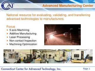
Innovative Fabrication Processes Are Being Assessed to Make Fusion More Competitive • New materials and processes may offer performance and/or cost savings • Laser-formed copper ST centerpost and TF/PF coils • FIRE is evaluating use of laser-formed TF and/or PF coils • Laser-formed Inconel TF coil structure (ARIES-AT) • Laser-formed ferritic steel vacuum vessel walls • Laser-formed vanadium blanket structure • Laser-formed divertor with graded tungsten surface layer ?? • Spray-cast aluminum ST return conductors (see supplemental data) • Boeing has submitted a white paper to VLT for developing advanced fabrication processes for fusion applications References are shown at end of presentation
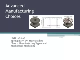
An Example • Problem Statement • The Spherical Tokamak’s copper center post was too expensive. • 30 m long, 850 tonnes • Water cooled • Leak tight construction • Complicated fabrication • Conventional Cost ~ $68M, ($80/kg) replaced every six years • Probably the most expensive component in the power core and certainly the highest annual cost item
Revolutionary Fabrication TechniquesMay Significantly Reduce Cost Boeing is funding AeroMet Corporation to develop a laser material lithography process to construct a part with minimal machining, thus reducing airframe material and fabrication costs. • Fabrication of titanium components (at right) are being considered for Boeing aircraft • Properties are equivalent to cast or wrought • Process is highly-automated (i.e., reduced labor) • In addition to titanium; SS316, H13 tool steel, IN625, and tungsten have been formed (copper is possible) • Process can produce parts with layered or graded materials to meet functional needs Conventionally-Machined Ti-6Al-4V Part
Theory of Laser Forming • A laser or plasma-arc deposits a layer of metal (from powder) on a blank to begin the material buildup • The laser head is directed to lay down the material in accordance to a CAD part specification • Like stereo-lithography, construction of overhanging elements should be avoided – tapers up to 60° are possible • Quantity of material constructed is limited only by the power of the lasers and the number of laser heads used • Surface finish of the parts is typically 32 to 64 µ in. and can be as good as 10 µ in.
Growing Centerpost With Laser Forming • An initial blank or preform plate will be used to start the centerpost. • Complex and multiple coolant channels can be enlarged or merged • Multiple heads can speed fabrication to meet schedule demands • Errors can be machined away and new material added during the fabrication
Examples of Fabricated Parts The machined laser-formed part shown above is a fracture critical component which has successfully passed both fatigue and static strength tests originally designed for the forged components which it will be replacing. It is approximately 36” (900 mm) by 12” (300 mm) by 6” (150 mm). This component was fabricated for The Boeing Company under funding from the Office of Naval Research. AeroMet Corporation has produced a variety of titanium parts. Some are in as-built condition and others are machined to final shape. Also see Penn State or SNL for additional information.
Cost Can Be Significantly Reduced Highly Automated Fabrication • Mass of centerpost with holes plus 5% wastage 894,000 kg • Deposition rate with 10 multiple heads 200 kg/h Total labor hours 8628 h • Labor cost @ $150/h (with overtime and site premium) $1,294,000 • Material cost, $2.86/kg (bulk copper alloy power cost) $2,556,000 • Energy cost (20% efficiency) for elapsed time + 30% rework $93,000 • Material handling and storage $75,000 • Positioning systems $435,000 • Melting and forming heads and power supplies $600,000 • Inert atmosphere system $44,000 • Process computer system $25,000 Subtotal cost of centerpost$5,122,000 • Contingency (20%) $1,024,000 • Prime Contractor Fee (12%) $738,000 Total centerpost cost$6,884,000 • Unit cost (finished mass = 851,000 kg) $8.09/kg < 3 x Matl Cost Compare to $80/kg with conventional fabrication ($68M)
Operational MTTR* Is Critical • A new power plant must have high availability to be competitive (< 85 - 90%) • Applies to both scheduled and unscheduled outages • Duration of outages are defined as MTTR/MTBF* • Plant must be designed for high maintainability • Modular power core sector replacement • Simple coolant and mechanical connections • Highly automated maintenance operations • Building designed for remote maintenance • Sectors can be repaired off-line • Better inspection means higher reliability * MTTR = Mean Time To Repair, MTBF = Mean Time Between Failure
Criteria for Maintenance Approach List does not imply priority • Reduce operational maintenance time • Improve reliability of replacement sector • Reduce cost (size) of building • Reduce cost of maintenance equipment • Reduce the cost of spares • Reduce the volume of irradiated waste • Reduce contamination from dust and debris • Must apply to scheduled and unscheduled maintenance • Increase reliability of maintenance operations (“failsafe” maintenance)
Cutout View Showing Maintenance Approach RAMI Results Show R&D Direction • Starlite Demo1-3 • •Define demonstrations • - Robotic maintenance • - Reliability • - Maintainability • - Availability • ARIES-RS4-9 • Integrate maintenance into power core • Design power core with removable sectors • Design high-temperature structure for life-limited components • Arrange all RF components in a single sector • Define and assess maintenance options • Define power core and maintenance facility • ARIES-ST10-12 • •Define vertical maintenance scheme • Remove centerpost only • Remove total power core • Use demountable TF coils • Split TF return shell • ARIES-AT13 • Improve maintainability • Refine removable sector approach • Define contamination control during maintenance actions • Assess maintenance options • Define maintenance actions • Estimate scheduled maintenance times Elevation View Showing FPC Maintenance Paths References are shown at end of presentation
Example of AT Sector Replacement Basic Operational Configuration Cross Section Showing Maintenance Approach Plan View Showing the Removable Section Being Withdrawn Withdrawal of Power Core Sector with Limited Life Components
Sector Removal Remote equipment is designed to remove shields and port doors, enter port enclosure, disconnect all coolant and mechanical connections, connect auxiliary cooling, and remove power core sector
ARIES-AT Power Core Removal Sequence Work in progress (1) Remove Shield (2) Move Shield to Storage Area (3) Remove Port Enclosure Door (4) Remove Vacuum Vessel Door (5) Move VV Door to Storage Area (6) Remove Core Sector (7) Transport Sector in Corridor (8) Exit Corridor Through Air Lock
ARIES-AT Maintenance Options Being Assessed • In-situ maintenance (not baseline approach) • All maintenance conducted inside power core • Replacement in corridor, hot structure returned • Life-limited components replaced in corridor, exo-core • Replace with refurbished sector from hot cell • (A) Bare sector transport • (B) Wrapped sector transport • (C) Sector moved in transporter (ala ITER)
Impact of Improved Maintenance on Power Core Design • Modified and enlarged TF coils from constant tension shape • Larger PF coils with higher stored energy • Increased port size for sectors or core • Modified power core structure • Required larger corridors and building These factors were integrated into power core designs and assessments
Summary of Fabrication and Maintainability Results • Advanced manufacturing processes can reduce the cost of components • Use of Advanced Manufacturing Processes on ARIES-ST TF coils predicted a 10% COE reduction • Power core designs suggest approaches for low mean time to repair (replace) • IF the availability can be increased from the usual 76% to 90%, the COE will decrease by 16% • Power cores and buildings must be designed with remote and highly automated handling in mind
References Advanced Manufacturing 1. L. M. Waganer, “Innovative, Ultra-Low Cost Fabrication Methods,” 18th IEEE/NPSS Symposium on Fusion Engineering, Albuquerque, NM, 25-29 October 1999. 2. L. M. Waganer, “Ultra-Low Cost Coil Fabrication Approach for ARIES-ST," to be published as a part of Final Report of ARIES-ST Study Results in Fusion Engineering and Design Journal, An International Journal for Fusion Energy and Technology 3. L. M. Waganer, “New, Ultra-Low Cost Fabrication Methods,” U.S./Japan Workshop on Fusion Power Plant Studies and Advanced Technologies, San Diego CA 16 -17 March 2000 4. F. Najmabadi, M. S. Tillack, A. Rene Raffray, S. C. Jardin, R. L. Miller, L. M. Waganer, and the ARIES Team, "Impact of Advanced Technologies on Fusion Power Plant Characteristics -- The ARIES-AT Study," to be presented at the 14th Topical Meeting on the Technology of Fusion Energy, ANS, Park City, UT, 15-19 October 2000. RAMI 1. F. Najmabadi, et al., "The Starlite Project: The Mission of the Fusion Demo,” 16th IEEE/NPSS Symposium on Fusion Engineering, Champaign, IL, 30 Sept - 5 Oct 1995 2. L. Waganer, et al., “What Must Demo Do?,” 16th IEEE/NPSS Symposium on Fusion Engineering, Champaign, IL, 30 Sept - 5 Oct 1995 3. M. S. Tillack, et al., “Engineering Options for U. S. Fusion Demo,” 16th IEEE/NPSS Symposium on Fusion Engineering, Champaign, IL, 30 Sept - 5 Oct 1995 4. M. S. Tillack and the ARIES Team, "Engineering Overview of ARIES-RS Tokamak Power Plant," 19th Symposium on Fusion Technology, Lisbon, Sept. 16-20, 1996. 5. L. M. Waganer, F. R. Cole, and the ARIES Team, "Designing a Maintainable Tokamak Power Plant" 19th Symposium on Fusion Technology, Lisbon, Sept. 16-20, 1996. 6. M. S. Tillack and the ARIES Team, "Engineering Design of the ARIES-RS Power Plant,” 4th International Symp. on Fusion Nuclear Technology, Tokyo, April 1997. 7. S. Malang, F. Najmabadi, L. M. Waganer, and M. S. Tillack, "ARIES-RS Maintenance Approach for High Availability,” 4th International Symp. on Fusion Nuclear Technology, Tokyo, April 1997 8. M. S. Tillack and the ARIES Team, "Configuration and Engineering Design of the ARIES-RS Tokamak Power Plant," FED Special Issue: ARIES-RS Tokamak Power Plant Design, FED 38 (1997). 9. L. M. Waganer, “The Configuration and Maintenance of the ARIES-RS Power Plant,”U.S./Japan Workshop on Fusion Power Plants, UCSD, San Diego, CA 3-5 March 1997. 10. X. R. Wang, F. Najmabadi, and M. S. Tillack, "Configuration and Maintenance Options for Low Aspect Ratio Tokamaks," 17th IEEE Symposium on Fusion Engineering, San Diego, CA, 6-9 Oct 1997. 11. F. Najmabadi and the ARIES Team, "The ARIES-ST Study: Assessment of the Spherical Tokamak Concept as Fusion Power Plants,” Proc. of 17th IAEA International Conference on Fusion Energy, Yokohama, Japan (1998). 12. X. R. Wang, M. S. Tillack, F. Najmabadi, S. Malang, "Configuration and Maintenance of the ARIES-ST Power Plant," Proc. of 18th IEEE Symp. on Fusion Engineering Albuquerque, NM Oct. 1999. 13. L. M. Waganer, “Comparing Maintenance Options for Tokamak Fusion Plants,” to be presented at the 14th Topical Meeting on the Technology of Fusion Energy, ANS, Park City, UT, 15-19 October 2000.
Good Material Properties Can Be Obtained Fatigue testing performed on laser-formed Ti-6Al-4V, showing performance at the low end of wrought material. Plotted against standard axial fatigue zones of cast and wrought Ti-6Al-4V, Ref Aeromet and DARPA. It is expected similar trends of properties would be obtained for copper. A variant of dispersion-strengthened copper may be possible with this process in the future.
Centerpost Cost Development • Part is 85% copper, 15% void for coolant passages, weighing 0.851 x 10⁶ kg • Part is cooled with room temperature water flowing in coolant passages along length of part • No water leaks are permitted to the surface • Nominal surface finish should be 64 µ in. or better including coolant passages • Part should be straight within reasonable requirements • Part will be fabricated on site in vertical position • Cost is 10th of a kind, 1998$ • Process hardware capital and energy cost included (may be capitalized in another cost account)
Spray Casting Is Attractive Fabrication Process for Outer TF Shell • Molten alloy metals (low-cost product form) can be atomized and sprayed onto a preform to fabricate a part • No overhangs without a preform • Fast deposition rates (0.5 kg/s/head or more) • Detail is less than laser forming (probably will need embedded tubing) • Minimal labor involved
Fabricating the TF Return Shell • TF shell has three parts: upper half, middle, and lower • Preform will be vacuum vessel - no cutouts or ports costed • Vacuum vessel will be 0.5” 5052 or 5002 aluminum plate for low resistance and ease of welding, and will serve as a form for spray casting • Individual VV segments (e.g. 30 orange slices, 15 m x 2 m for upper half) will be bump formed into shape and welded • Remainder of VV shell thickness (0.5 to 2.5 m) will be spray cast to final shape and thickness • Flanges and other features can be spray cast • Stainless steel coolant tubes will be embedded in spray cast material
Aluminum TF VV Cost Analysis • Mass of 1/2”-thick plates, incl. wastage 41,765 kg • Material cost: $5/kg (aluminum alloy plate) $208,825 • Bump forming: 90 panels x 60 h/panel 5400 h • On-site weld setup: 6 mo x 6 people x 160/mo 5760 h • Weld prep: 90 panels x 2 h/m + setup(10 h/panel) 4776 h • Segment welding: 900 m x 0.13 h/m ÷ 25% efficiency 472 h • Weld inspection: 900 m x 1 h/m 900 h • He leak check: 900 m x 0.5 h/m 450 h • Final cleaning for vacuum service 1500 h Total labor hours 19,258 h • Labor cost @ $120/h (including site premium) $2,310,960 Subtotal $2,519,785 • Contingency (20%) $503,957 • Prime contractor fee (12%) $362,849 Total cost of vacuum vessel $3,386,591 • Unit cost (finished mass = 39,776 kg) $85.15/kg 2-3 yrs elapsed time This unit cost is representative of conventional fabrication
TF Return Shell Cost Development • Molten aluminum slightly above the melting temperature is sprayed on the vacuum vessel preform to build up the thick outer TF shell (0.5 to 2.5 m thick). • Part is 85% aluminum, 15% void for coolant plus SS tubes. • Operationally, the aluminum shell is cooled with room temperature water flowing through embedded stainless steel coolant tubes. • Flanges and fittings not included, but additional cost would be minimal. • Part will be fabricated on site. Upper shell is built in place; middle and lower shells are built upside down, inverted, and moved to power core area. • A fabrication room (30 m dia. x 20 m high) will be required. • Cost is 10th of a kind, 1998$; fabrication hardware and energy cost included.
Schematic of Spray Casting Process Molten Metal Furnace, Courtesy of SECO/WARWICK, Inc.
Spray Cast Shell Cost Analysis • Mass of three shell components 2,690,000 kg • Including wastage of 5%2,820,000 kg • Deposition rate per head (4 heads used) 0.5 kg/s • Build labor, 1 operator + 1 assistant/inspector, 50% efficiency 1569 h • Inspection and rework 400 h Total labor hours 2089 h • Labor cost @ $150/h incl. site premium $313,375 • Material cost, $1.87/kg (aluminum) + tubes $5,331,815 • Energy cost, natural gas + pump electrical $37,398 or $37,398 • Melting and handling furnaces include installation $2,650,000 $985,000 • Other fabrication hardware $1,379,000 $1,379,000 Subtotal $9,711,588 $8,046,588 • Contingency (20%) $1,942,318 $1,609,318 • Prime contractor fee (12%) $1,398,469 $1,158,709 Total cost of spray cast shell $13,052,375 $10,814,615 • Unit cost (finished mass = 2,020,000 kg) $4.85/kg $4.02/kg SECO/Warwick* Schaefer* * SECO/Warwick and Frank W. Schaefer, two well-known furnace manufacturers, provided ROM estimates based on limited information. These data should be considered as a range, not company specific.
TF Coil Cost Summary Component Finished Mass Total Cost Unit Cost Cu Centerpost 0.851 Mkg $6.88 M $8.09 TF Vacuum Vessel 0.040 Mkg $3.39 M$85.15 Al Spray Cast Shell 2.690 Mkg $11.93 M(average)$4.44 TF Coil System 3.581 Mkg $22.20 M(average)$6.20 (minimum) $5.89 (maximum) $6.51 We recommend using this low-cost, automated fabrication technique for Centerpost and TF Return Shell. It has the promise of reducing the capital costs by $200-300M and lowering the COE by ~ 10%.
Summary Remarks • These two innovative metal fabricating techniques can provide significant cost savings over convention fabrication techniques if material properties are adequate and the parts are suitable for the processes. • If the processes can be perfected, it will help reduce the cost of many products. It is not unique to spherical tokamaks. • They are well suited to replace labor-intensive or metal-removing intensive processes.