Download
1 / 19
190 likes | 209 Views
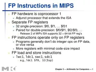
MIPS I/O and Interrupt. Review. Floating point instructions are carried out on a separate chip called coprocessor 1 You have to move data to/from coprocessor 1 to do most common operations such as printing, calling functions, converting number, etc

E N D
Review • Floating point instructions are carried out on a separate chip called coprocessor 1 • You have to move data to/from coprocessor 1 to do most common operations such as printing, calling functions, converting number, etc • There are 32 floating point registers, $f0 - $f31 • You can access all 32 with single precision instructions • You can only access even numbered registers with double precision instructions
Review • Floating point instructions use the following abbreviations: • s – single precision • d – double precision • w – integer (word) • c1 – coprocessor 1 • mt/mf – move to / move from • cvt – convert • bc1t / bc1f – branch if true/false • c – compare
Review • Questions that were asked last class: • What delimiter is used to construct an array of double precision numbers? • .double • Also, .byte and .half construct arrays of 8bit and 16bit values respectively • Can you move a double precision number to a word in the main processor? • Yes. • There is a psudo instruction that moves the values from two floating point registers (a double) to two main registers. The first parameter is a main register and the floating point number is stored here and in the main register immediately following it. E.g if you specify $t0, it will store into $t0 and $t1 • mfc1.d $v0, $f0 • Other choices available: • Convert to single precision then move • cvt.s.d $f9, $f0 • mtc1 $v0, $f9 • Same as the psudo instruction, but can pick the registers you want • mtc1 $s0, $f0 • mtc1 $t0, $f1 • Are there other flags you can use in coprocessor 1? • Yes, there are 8 flags you can use from 0 to 7 • Ex. c.le.s 4 $f0, $f1
SPIM I/O and MIPS Interrupts • The materials of this lecture can be found in A7-A8 (3rd Edition) and B7-B8 (4th Edition). • The material covered here will only make a brief appearance on the midterm and won’t be on the final nor any exercises / homeworks • It is mainly used to give you a background for future classes such as Computer Organization II and Operating Systems
The MIPS memory • Actually, everything above 0x7fffffff is used by the system.
What is in there? • Special operating system functions • I/O registers mapped to memory addresses • Kernel data • …
SPIM Input • SPIM allows you to read from the keyboard (which is similar to reading something from the true I/O register)
.text .globl main main: li $s0, 'q' # q key lui $t0, 0xFFFF # $t0 = 0xFFFF0000 waitloop: lw $t1, 0($t0) # load control byte andi $t1, $t1, 0x0001 # check to see if new data is there beq $t1, $zero, waitloop # loop if not lw $a0, 4($t0) # load data byte beq $a0, $s0, done # exit if 'q' is typed li $v0,1 # print integer syscall li $v0,4 # print string la $a0, new_line syscall j waitloop done: li $v0, 10 # exit syscall .data new_line: .asciiz "\n" • Remember to select ``mapped I/O’’ in PCSpim settings. • To set it, select ``Simulator’’ then ``Settings…’’
SPIM output • Similar to the input, SPIM has two memory locations for output • 0xffff0008: Transmitter control. • Bit 1: interrupt enable • Bit 0: ready • 0xffff000c: Transmitter data. • Bit 0-7: data byte
SPIM output • If you need to show something on the console, do the following: • Check if ready bit is 1. If yes, proceed. Otherwise, wait. • Write to the data. The ready bit will be reset to 0, and will be set to 1 after the byte is transmitted.
question • Is this the most efficient way to do it? • Remember that the processor usually has a lot of things to do simultaneously
Interrupt • The key problem is that the time when the input occurs cannot be predicted by your program • Wouldn’t it be nice if you could “focus on what you are doing” while be “interrupted” if some inputs come?
MIPS interrupt EPC=0x00000128 EPC= something • With external interrupt, if an event happens that must be processed, the following things will happen: • The address of the instruction that is about to be executed is saved into a special register called EPC • PC is set to be 0x80000180, the starting address of the interrupt handler • which takes the processor to the interrupt handler • The last instruction of the interrupt should be “eret” which sets the value of the PC to the value stored in EPC a a add $t0, $t1, $t0 a a sub $t2, $t1, $t0 a a sub $t0 $s0, $a0 0x00000128: a a sll $t0, $t0, 2 . . . 0x80000180: a a add $k0, $k1, $k0 a a sub $k1, $k0, $k1 a a eret
MIPS Interrupt EPC= something EPC=0x00000128 t0= 10 t0= something t0= 3000 • Is it okay to use $t0 in the interrupt? • Note the difference between an interrupt and a function call. • For a function call, the caller is aware of the function call, so, it is not expecting the value of $t0 to be the same after the call. • For an interrupt, the user program is running and gets interrupted. The user program does not know about the interruption at all. • So, if you changed $t0 inside an interrupt, after the interrupt returns, the user program will not even be aware of the fact that it has been interrupted, and will use the wrong value of $t0. a a add $t0, $t1, $t0 a a sub $t2, $t1, $t0 a a sub $t0 $s0, $a0 0x00000128: a a sll $t0, $t0, 2 . . . 0x80000180: a a add $k0, $k1, $k0 a a sub $t0, $k0, $k1 a a eret
MIPS Interrupt • $k0 and $k1 are both used as temporary variables in interrupt servicing routines.
Interrupt • Interrupt handlers should be short. • Usually should just use the interrupt to set some flags, and let the main program to check the flags • Flags can be registers and can be checked much faster than reading the value of an external pin or reading data from other chips
.kdata # kernel data s1: .word 10 s2: .word 11 new_line: .asciiz "\n" .text .globl main main: mfc0 $a0, $12 # read from the status register ori $a0, 0xff11 # enable all interrupts mtc0 $a0, $12 # write back to the status register lui $t0, 0xFFFF # $t0 = 0xFFFF0000 ori $a0, $0, 2 # enable keyboard interrupt sw $a0, 0($t0) # write back to 0xFFFF0000; here: j here # stay here forever li $v0, 10 # exit,if it ever comes here syscall .ktext 0x80000180 # kernel code starts here sw $v0, s1 # We need to use these registers sw $a0, s2 # not using the stack because the interrupt # might be triggered by a memory reference # using a bad value of the stack pointer mfc0 $k0, $13 # Cause register srl $a0, $k0, 2 # Extract ExcCode Field andi $a0, $a0, 0x1f # Get the exception code bne $a0, $zero, kdone # Exception Code 0 is I/O. Only processing I/O here lui $v0, 0xFFFF # $t0 = 0xFFFF0000 lw $a0, 4($v0) # get the input key li $v0,1 # print it here. syscall# Note: interrupt routine should return very fast, so # doing something like print is NOT a good practice! li $v0,4 # print the new line la $a0, new_line syscall kdone: lw $v0, s1 # Restore other registers lw $a0, s2 mtc0 $0, $13 # Clear Cause register mfc0 $k0, $12 # Set Status register andi $k0, 0xfffd # clear EXL bit ori $k0, 0x11 # Interrupts enabled mtc0 $k0, $12 # write back to status eret # return to EPC
MIPS interrupt • Coprocessor 0 is a part of the CPU to handle interrupts. In SPIM, Coprocessor 0 contains the • BadVAddr (8), storing the memory address causing the exception • Count (9), increment by 1 every 10ms by default • Compare (11), if equals to Count, trigger an interrupt of level 5 • Status (12), • Bit 8-15: interrupt mask. A bit being ``1’’ means that this interrupt is enabled. • Bit 4: user mode. With SPIM, always 1. • Bit 1: exception level (EXL). Normally ``0,’’ set to ``1’’ if an exception occurred. When ``1,’’ no further interrupt is enabled and EPC is not updated. • Bit 0: interrupt enable. Enable (``1’’) or disable (``0’’) all interrupts. • Cause (13) • Bit 8-15: pending interrupts . A bit being ``1’’ means that this interrupt situation occurred, even if it is not enabled. • Bit 2-6: Exception code. ``0’’ is hardware interrupt. • EPC (14) • Config (16), config the machine • These registers can be read and modified using the instructions mfc0 (move from coprocessor 0) and mtc0 (move to coprocessor 0).