Download
1 / 27
270 likes | 376 Views
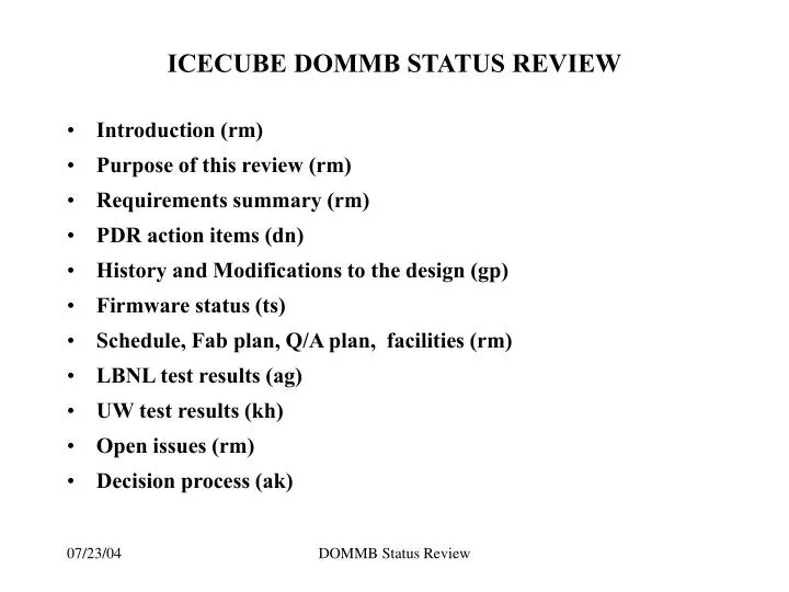
ICECUBE DOMMB STATUS REVIEW. Introduction (rm) Purpose of this review (rm) Requirements summary (rm) PDR action items (dn) History and Modifications to the design (gp) Firmware status (ts) Schedule, Fab plan, Q/A plan, facilities (rm) LBNL test results (ag) UW test results (kh)

E N D
ICECUBE DOMMB STATUS REVIEW • Introduction (rm) • Purpose of this review (rm) • Requirements summary (rm) • PDR action items (dn) • History and Modifications to the design (gp) • Firmware status (ts) • Schedule, Fab plan, Q/A plan, facilities (rm) • LBNL test results (ag) • UW test results (kh) • Open issues (rm) • Decision process (ak)
Introduction • Next round of cards is intended for circuit development and as a test bed for the procedures to be used for producing 420 production boards in the Spring of 2004, including: • production facilities • burn-in and cold testing • test procedures and recording of data • documentation • quality assurance • characterization of yield and variations in individual performance • preparation for Production Readiness Reviews • The boards will be incorporated in Optical Modules at UW and elsewhere. This will enable development and testing of OM production facilities. • Testing of the integrated modules • Testing of a prototype string.
Purpose of the review • This review addresses several questions: • What are the requirements missing from the Requirements Document that would affect MB hardware other than those already identified at the MB requirements reviewed at the PDR of 5/20/03 at UW. • What tests of MB functionality and performance need to be done on board level and system level to show the MB design meets requirements. • What additional tests must be done before prototype fabrication can begin. • Is the quality of the present tests adequate? The review will establish items for action prior to fabrication and a process for approval to proceed with fabrication.
Requirements summary • 6.2 Performance Requirements • 6.2.1 Time Resolution • 6.2.2 Time-Stamped Data • 6.2.3 Signal Path Recovery from Saturation • 6.2.4 High Speed PMT Waveform Capture • 6.2.5 Medium-Speed PMT Waveform Capture • 6.2.6 Instantaneous Dynamic Range • 6.2.7 Integral Dynamic Range • 6.2.8 PMT Gain, Stability, and Resolution • 6.2.9 PMT Linearity, and Calibration Accuracy • 6.2.10 Analog Signal Path Signal/Noise Ratio
Requirements (contd) • 6.2.11 Discriminator Threshold Range and Resolution • 6.6.12 PMT Discriminator Threshold Stability • 6.6.13 Calibration Pulser (light or charge) • 6.6.14 PMT Noise Rate Measurement • 6.6.15 DOM MB Operation in Master/Slave Mode • 6.6.16 One or Two DOMs per Twisted Pair • 6.6.17 DOM MB Data Transmission for In-Ice Devices • 6.6.18 DOM MB Data Transmission for Ice-Top • 6.6.19 Data Compression/Feature Extraction for In-Ice Devices • 6.6.20 Data Compression/Feature Extraction for Ice-Top
Requirements (contd) • 6.6.21 Robust Bootstrap Scenario • 6.6.22 Simultaneous DATA Acquire/Transmit • 6.6.23 Local Clock Short-Term Stability • 6.6.24 Cable Length Measurement by RAP • 6.6.25 Maximum Sustainable Rate • 6.6.26 Pressure Sensor • 6.6.27 Temperature Sensor
Open issues from PDR • See presentation by Dave Nygren • (R. Minor D. Nygren Open) • Signal droop and signal recovery. • requirements for the on-board LED pulser and its calibration. • Supernova detection / noise rate • Data extraction requirements • Local clock trade study • Change Dynamic Range from 2000 to 10000 <PE>. • LED light attenuation • (R. Iliff R. Paulos Open) • System power allocations • Electromagnetic susceptibility
Verification methods • Typical methods • Inspection, Demonstration, Analysis, Test • Board level vs System level tests
Development History • See presentation from G. Przybylski
Modifications for rev #3 • See presentation from G. Przybylski
Firmware status • See presentation from T Stezelberger
Rev 3 design Status • Schematic updated • Parts list updated • Parts on order, latest delivery August 20th • Layout in progress • ATWD tester may be available for partial testing
Schedule • This review July 23rd • Close out action items • Finalize layout • Decision to proceed required by 8/18/03 • Fab and load pcbs 8/18/03 – 9/12/03 • Q/A Testing 9/1/03 – 9/26/03 • First cards to Wisconsin 9/1/03 • Last cards to Wisconsin 9/26/03 • Integration and testing 9/1/03 – 12/31/03 • Long lead parts order for 420 cards 11/1/03 • Construction readiness review for 420 cards 1/15/04
Fabrication plan • To minimize risk during fabrication • Net verification of layout • Three pcb vendors being qualified • Two assembly houses being qualified • 100 cards to be fabricated • First article of 6 loaded cards tested prior to commitment of remaining parts to verify that circuit modifications are correct. • 80 cards delivered for integration (reworked cards only on a case by case basis) • 20 cards at LBNL for support of software development • Cards not passing tests will be debugged, analysed, & reworked • Engineering run this fall as a final production model if needed
Fabrication plan (contd) • PCB fab for reliability (class 2+) • Material selection for BGA compatibility • Critical Process controls added: • Electroless plating - run weight gain coupons with each tank load to verify copper thickness is acceptable • Electroplate - plate .001 -.0015 copper in the hole and verify with microsection from each tank load • No micro welds allowed • Assembly for reliability (class 2+) • Parts tracking during loading • Improved tab structure, tab removal and carrier for handling • 3D x-rays of BGAs • Delay card added at vendor • Conformal coating if required at vendor for production • Carrier for pc cards, shipping containers specified by Icecube
Q/A plan • Recent experience dictates additional testing of pc cards during fab: • PCB continuity test before and after temp cycle • Thermal cycling test – coupons and/or boards • Derived from milspec 55110, IPC-TM 650 • Recent experience indicates additional testing of loaded cards: • Full temperature cycling -45 to +50 deg C in place of simple burn-in • Run of 100 may only have partial temp cycle
Budget • Originally 200 cards > 150 > 120 >80 • Parts ordered for minimum of 100 • Fab 100 deliver 80 (20 for analysis) • Engineering run (4 cards) in parallel
Staff and Facilities • Facilities • 50A 6113 available for run of 100 • Additional space for 500 being negotiated
Open issues • Requirements action items • Other new requirements ( IceTop and other) • Characterization tests: • RAP test must be completed • Ringing investigation • ATWD baseline shift investigation • Verification matrix • Final parts selection, availability and cost • Final selection of pcb and assembly vendors • Finalize STF & test plan • Documentation and database • Coupon or boards for pre-load pcb temperature test? • Range and number of burn-in/temperature cycles for workmanship screening without impairing the boards? • Temperature for final Q/A test = -45 DegC?
Decision process • Albrecht
History: Prototype I • 4 cards loaded • Cold start – memory • Shorts from ORCAD translation • Power supply details • Interim parts list – parts availability • Layout details – trace routing, silkscreen etc • Reversed control lines on memory • Power reversal on sdram • Lookback memory reversed power leads • Flasher interface not established • Mechanical exclusion areas not defined or met • Reversed diode
History: Prototype II • 28 cards fabricated • 7 of 19 tested had problems other than configuration • Cold boot – pld delay • AD830 – vendor error • Missing parts when loaded • Memory misloaded • Reversed diodes • Schematic error – cap polarity • Schematic error - missing trace in clock comparator • Bad transistor in over-voltage circuit • Bad traces (4) • Bad ATWD (1) • Bad ferrite beads (2) • BGA (2) • Baseline shift
Modifications for next run • Q/A tests added to plan • EPXA4 baselined incl configuration memory • Power, gnd for EPXA4 corrected • Unused memory removed • Provision for Toyocom and Corning clocks • Clock distribution modified • Two 12 channel ADCs • Trace conflicts removed • Parts consolidation • Hirel capacitors selected • Test connector • Connector for delay line • ADC options added (12 vs 10 bits) • Parts relocated for integration • HV power supply connector • Power supply layout optimized • Removed unused test connector • DAQ reference rerouting