Download
1 / 21
270 likes | 589 Views
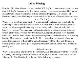
Biasing Modes for Diodes. Diodes have two biasing modes: Reverse biasing : diode current (ID) is almost zero. The only current is the reverse saturation current (Is or I 0 ). Forward Biased Diode. Forward Biasing:

E N D
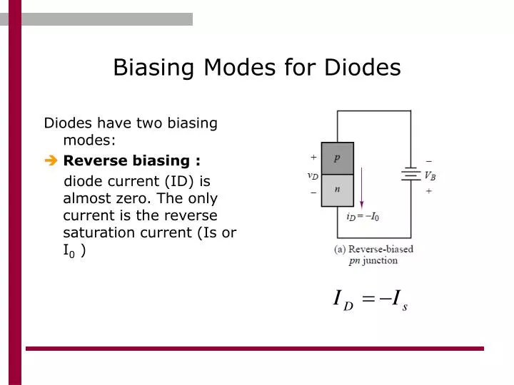
Biasing Modes for Diodes Diodes have two biasing modes: • Reverse biasing : diode current (ID) is almost zero. The only current is the reverse saturation current (Is or I0 )
Forward Biased Diode • Forward Biasing: diode current (ID) is the difference between diffusion current (Id) and reverse saturation current (Is). VT = 0.025 volts at room temperature (Thermal Voltage)
IdealCurrent-Voltage (I-V)Characteristics The p-n junction only conducts significant current in the forward-bias region. iD is an exponential function in this region. Essentially no current flows in reverse bias.
Circuit Symbol Conventional current direction of the Diode (ID) is from P-type to N-type. polarity of voltage drop (VD) is as shown in the figure.
Diode Breakdown voltage • Happens when a large reverse voltage applied to the diode. • At breakdown the diode conducts current in the reverse direction. • The magnitude of the breakdown voltage (BV) is smaller for heavily doped diodes as compared to more lightly doped diodes.
Cct. Models for semiconductor diodes Diode Models Large Signal Small Signal Piecewise Linear Ideal Diode Offset Diode
Large Signal Vs. Small signal Models • In small signal model, the exact I-V char. Curve is used to determine diode voltage and current it is used to determine accurate operating point of the diode. • Large signal models use approximating I-V char. Curve and thus approximate results of diode voltage and current.
Large signal ideal diode model • treats the diode as a simple on-off device. • The analysis of a circuit containing a diode may be greatly simplified by using the short-circuit–open-circuit model. approximated by an open circuit when vD < 0 approximated by short circuit when vD ≥ 0
Large signal ideal diode model • For Ideal diode model we assume the following: • Cutoff frequency Vγ=zero • Reverse Biased current =zero • Internal resistance of the diode=zero (no limiting resistance for the forward current)
How to solve circuits with diodes ??? • Diodes are considered non-linear elements since it has non-linear I-V char. Curve. • If we have a diode in a circuit we need first to determine the conductionstate of the diode (Forward or Reverse) (conducting or not) • After the state is determined, we can replace the diode with open or short circuit (linear elements) • Finally we solve the resulting linear circuit using one of the linear DC circuit analysis techniques.
Circuits with more than one diode • Assume a state for each diode, either “on” or “off” (conducting state) • (2) Assume a short circuit for diode “on” and an open circuit for diode “off” • (3) Check to see if the result is consistent with the assumed state for each diode (current must flow in the forward direction for diode “on” and the voltage across the diodes (VD) assumed to be “off” must be positive at the cathode – reverse bias) • (4) If the results are consistent with the assumed states, the analysis is finished. Otherwise return to step (1) and choose a different combination of diode states.
Nodal analysis Mesh analysis Kirchhoff’s voltage law Thevenin & Norton theorems Example 1: Diode in DC circuit DC Circuit containing ideal diode • We can use Kirchhoff's voltage law and Kirchhoff's current law. • Thevenin and Norton Theorems can also be used.
Example 1: Ideal Diode in DC circuit (cont.) • First, we assume diode is not conduction (open circuit) • Then check VD value. • If positive assumption wrong Diode is short • If Negative assumption correct diode is open • Then replace the diode by open or short. • Finally solve the linear circuit. VD = 1.5 > 0 Assumption wrong Diode should be shorted
Example 1: Ideal Diode in DC circuit (another approach) • First, we assume diode is conducting (short circuit) • Then check ID direction. • If ID from P to N side assumption correct Diode is short • If ID from N to P side assumption wrong diode is open • Then replace the diode by open or short. • Finally solve the linear circuit. ID= 1.5 mA (from P to N side) Assumption correct Diode should be shorted
Example 2 : Diode in DC circuit • We assume it is open. • We find VD to be (-3 volts) 3) Our assumption is correct (the diode is open. • Determine the conduction state of the diode.
Practice Determine if the diode is on or off. ?
More than one diode in a circuit. * Find the diode states by using ideal-diode model. Starting by assuming both diodes are on.