Download
1 / 6
60 likes | 136 Views
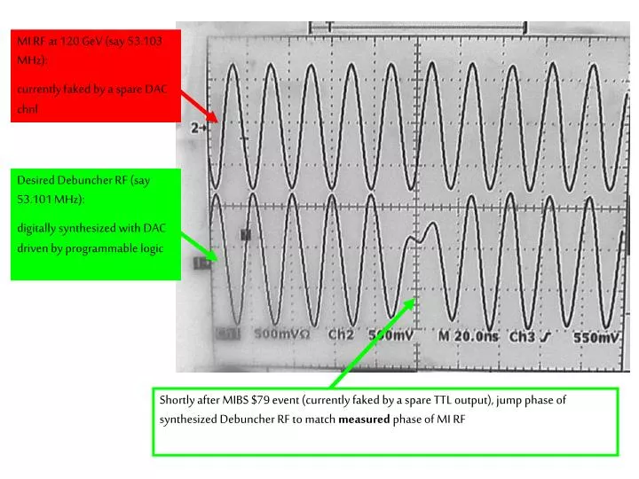
MI RF at 120 GeV (say 53.103 MHz): currently faked by a spare DAC chnl. Desired Debuncher RF (say 53.101 MHz): digitally synthesized with DAC driven by programmable logic.

E N D
MI RF at 120 GeV (say 53.103 MHz): currently faked by a spare DAC chnl Desired Debuncher RF (say 53.101 MHz): digitally synthesized with DAC driven by programmable logic Shortly after MIBS $79 event (currently faked by a spare TTL output), jump phase of synthesized Debuncher RF to match measured phase of MI RF
Jump Debuncher phase (before cavities turn on) Measure MI phase here
Next revision of digital damper board may live in a VME (or similar) crate, to simplify the infrastructure needed. But this works pretty well.
DAC output (x4) 12 bit, 424 MS/s Ethernet (Acnet etc) CPU slow control FPGA signal processing Altera EP1S25: lots of fast programmable logic; built-in RAM, PLLs, multipliers; 672 pins; can drive LVDS, TTL, ... ADC input (x4) 12 bit, 212 MS/s TTL I/O
The FPGA coding looks like something in between writing a program and drawing a schematic.
Status • Adapted damper board seems to work in self-test mode. Measures phase to <0.1°. Still some testing/tweaking to be done. • Talks to acnet (but haven’t yet made acnet devices specific to this application, e.g. debuncher frequency setting). • AP50 network connection due Monday. Plan to go to AP50 with Dave Peterson, plug in inputs (copy of MI RF signal and MIBS $79 trigger), then observe output signal and Debuncher BPM signal on a scope. • I think I can plug in by bypassing existing Debuncher 53 MHz VCO, whose output is labeled as a BNC cable on the schematic, but need to check on this. Need to learn to switch over and back (for tests) without risk to stacking operations. Then need to schedule tests. • Need pulse-by-pulse diagnostic measurement of relative phase of Debuncher RF and incoming beam. (In principle the damper board could provide this, by measuring phase of BPM or RWCM signal.) • Is it easier, for an initial test, to move the Debuncher frequency a bit (e.g. 100 Hz) or to move the MI 120 frequency a bit (e.g. radial position)?