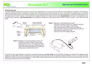
Download
1 / 38
380 likes | 489 Views
Page A6a. Schematic Analysis for Sequence of Operation ( AUTOMATIC Glow Coil System). Please turn to page A6a. Sequence of Operation. Before we begin the sequence of operation, there are some details on the schematic that need to be reviewed. Please make the following

E N D
Page A6a Schematic Analysis for Sequence of Operation (AUTOMATIC Glow Coil System)
Before we begin the sequence of operation, there are some details on the schematic that need to be reviewed.
Please make the following notes on your page A6a.
This is the baso switch. The contacts are shown. The coil that is energized by the thermocouple, is not shown.
The wire coming from the transformer to this ‘R’ terminal is the ‘P’ (POWER) side of the 24v.
What does that make this terminal? P
I hope you answered ‘C’ for common. P C
A thermostat is not shown, but for heating it would complete the circuit between the ‘R’ and ‘W’ terminals. P C
24v from the ‘P’ terminal goes to the ‘R’ terminal of the terminal strip, then to the thermostat and back from the thermostat to the ‘W’ terminal of the terminal strip. P C
The ‘Fan Time Delay’ switch is used during heating. You will notice the 24v has arrived at the one terminal of the switch and if you look to the left you will see another terminal. If you follow the wire on that terminal, it returns to the ‘C’ of the control transformer.
This switch has a heater inside that will take some time to heat up (approximately 90 to 120 seconds) and then close the contacts to the fan. This switch is used instead of a heat sensitive bimetal FAN switch.
I hope you answered NC. But look at the LS on this schematic from the manufacturer. They drew it NO but labeled it NC. Your experience tells you it should be NC, so you conclude it is labeled correctly but drawn incorrectly. This happens, so you really need to know your symbols and function of the symbols to help out in this situation.
24v continues on to the gas valve, through the gas valve to the NO contacts of the Baso switch, which is a dead end. P C
Now that we have come to a dead end, we need to back up and follow a different path on the schematic.
We are going to back up and start again at the ‘P’ terminal of the control transformer. We come out of the ‘P’ terminal and go to the ‘Pilot Pressure Switch.’ P C
The ‘Pilot Pressure Switch’ is a pressure dependent switch. When pilot gas pressure is present, the switch closes and will allow the pilot to be lit. If no pressure is available in the pilot tube leading to the pilot assembly, there is no reason for trying to light the pilot. So the pilot pressure switch ‘proves’ there is pilot gas pressure present.
Since it is dependent on pressure to ‘close’ you would expect the symbol to be shown NO, which it is on the schematic. But notice the identification of its position is marked NC. So here again we have the manufacturer making a mistake and we have to be the wiser to figure it out. The switch should be ‘open’ and so marked NO.
Proceed once again with the schematic assuming there is pilot gas present and the pressure in the pilot tube will have the switch ‘closed.’
The voltage will flow through the pilot pressure switch, through the PRIMARY of the ignition transformer, to the NC contacts of the Baso switch, through the Baso switch to the ‘C’ terminal and then on back to the ‘C’ terminal of the control transformer.
P C
What happens now?1. Secondary of the ignition transformer is energized and provides 2.5v to the glow coil.2. The glow coil will get hot and the pilot gas will light.
3. The flame will strike the tip of the thermocouple and when it produces it mv (millivolts), the Baso switch NO contacts will close, and the NC contacts will open.4. The ignition circuit is de-energized and the glow coil will cool off.
5. The main gas valve circuit will ‘make’ and the main valve will open for gas to flow to the main burners.So let’s look at the schematic and see it happen.
P C
This completes the sequence of operation for the automatic glow coil system.