Download
1 / 176
1.76k likes | 1.86k Views
LESSON 1 MONITOR TANK CLEANING, VAPOR FREEING, CLEAN STORAGE TANKS. INTRODUCTION Tank cleaning is a task that should not be approached lightly as there are many hazards involved in the process. These hazards are lead, hydrogen sulfide, and explosive vapors, just to mention a few. If you find

E N D
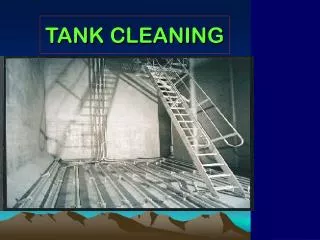
LESSON 1 MONITOR TANK CLEANING, VAPOR FREEING, CLEAN STORAGE TANKS
INTRODUCTION Tank cleaning is a task that should not be approached lightly as there are many hazards involved in the process. These hazards are lead, hydrogen sulfide, and explosive vapors, just to mention a few. If you find yourself in a position to supervise the cleaning of storage tanks, you must be thoroughly familiar with these hazard
PART A - DESIGN AND USAGE OF PETROLEUM STORAGE TANKS The following factors that must be considered when designing and using petroleum storage tanks: Losses result from filling, breathing, and seepage. Filling loss: As an atmospheric storage tank is filled, the vapor above the product will be forced out of the tank which results in a loss of product. Breathing loss: An atmospheric storage tank used for static storage will lose product as vapors are forced out of the tank due to the expansion of the product as it heats up during the day. Conversely, as the product cools and contracts, the air will be drawn in. Seepage loss: Due to small ruptures in the tanks.
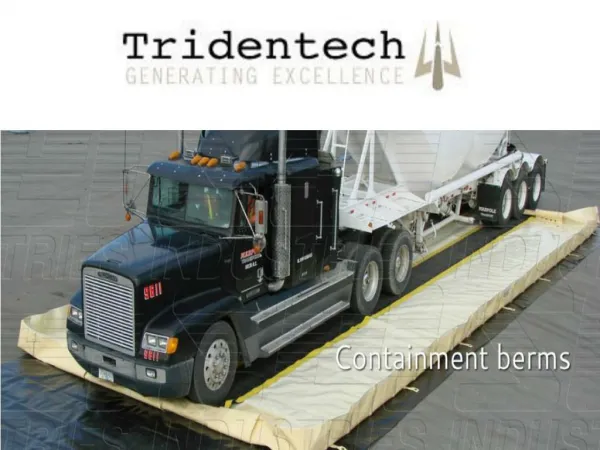
Security against fire hazards: Escaping vapor: Vapors, being heavier than air, will tend to seek low spots and will present hazardous conditions. This is particularly dangerous during filling operations. Leaks: Leaks are always a hazard and must be corrected as soon as observed. Real estate: The proximity of storage tanks to one another and other facilities must be taken into consideration when surveying potential hazards. Firewalls, dikes and berms, must be constructed in order to minimize some of the risks involved with bulk petroleum storage and distribution.
PART B - TYPES OF TANKS Keeping in mind the problems we have just discussed, let us classify and discuss the various types of tanks according to the job they will do so that we can employ them to best solve the problem. Fixed Roof Tanks. Bolted steel cone roof. This is the type used extensively by the military. It comes in various sizes and is classified as semipermanent and can be moved. This tank cannot withstand pressures of more than 1 to 3 ounces (oz.) per cubic in. and a vacuum of no more than 1/2 oz. cubic inch. For this reason, the tanks have free vents and have a high vapor loss. Welded steel cone roof. This type of tank is the most commonly used tank for permanent installations. Because of the construction, it requires skilled personnel. This type of tank will withstand pressures from 3 to 8 oz. cubic inch in a vacuum of 1/2 oz. per cubic inch and is equipped with pressure vacuum vents. For this reason, the welded cone roof tank is better suited for the storage of high volatile products than the bolted steel tank.
Floating Roof Tanks. The floating roof “floats” on the surface of the product and virtually eliminates breathing and filling loss. There are three types of floating roofs which we will discuss. Pan type. A large, floating pan, slightly smaller in diameter than the tank shell. A system of flexible “shoes” closes the space between the edge of the roof and the tank shell. Pontoon type. System of closed compartments or “pontoons” to increase floating stability and simplify the structure. Double deck. Two separate decks over entire back surface. Provides insulation from the sun’s rays and cuts down on loss of product from evaporation. All tanks with floating roofs have a wind girder around the top edge to stiffen the shell when the roof is down. Many commercial firms and Air Force bases employ these tanks for gasoline and JP4. (Best adapted where tanks are filled and tied frequently.) They are somewhat of a maintenance problem because of the sealing material used between the tank shell and the roof.
Cone Roof With Floating Pan. Floating roof tanks present a problem in cold climates because of the accumulation of ice and snow. Because of this problem, floating roof tanks can be modified and a fixed roof installed. This procedure employs the advantages of the fixed roof and the floating roof.
Underground Tanks. Construction. Underground tanks are coated with a coal tar coating to prevent corrosion. They may have a concrete supporting wall around the exterior surface. Vapor loss. Underground tanks also come equipped with deepwall pumps and pressure vacuum vents. Because of the stabilized temperature (mid 50s), underground storage tanks have very little vapor loss. Leakage. Leaks in underground storage tanks are very hard to detect and may show up in water tables after the leak has occurred.
Cut and Cover Tanks. Cut and cover tanks are constructed by scooping out a hole or depression in the earth, setting a steel storage tank in the cut, and covering it with earth so that the only part of the structure above ground would be a small shack or manhole and vent to permit access to the tank and allow excessive vapors to escape.
PART C - TANK ACCESSORIES Pressure-vacuum vent. The pressure and vacuum vent (breather valve) (Figure 1-1) is an automatic device designed to reduce evaporation loss and to help relieve excessive pressures or vacuums built up during operations or as a result of atmospheric temperature variations. The vent consists of a pressure section and a vacuum section. Each section opens according to a predetermined setting. To ensure efficient operation, vents should be inspected monthly. Flame arrester. Flame arresters (Figure 1-2) are used to prevent flashback into a tank in case of fire. The flame arrester is usually placed between the roof and the vent. One type of flame arrester consists of a tight coil of fine wire mesh enclosed in a heavy casing which is flanged to the roof.
Manometer. Manometers are installed on the roofs of floating roof tanks to facilitate gaging. They are used to measure the difference between the level of product in the tank and the level of product in the gaging well, and to subsequently arrive at an accurate gage. Gage hatch. Self-explanatory. Individuals involved in gaging should be careful not to drop articles down the gaging hatch in as much as this has a bad effect on the product and also might block valves and damage pumps. Manhole (or clean out door). Opening designed to permit entry for such purposes as cleaning the tank and making repairs. Grounding. Some tanks are inherently grounded by their contact with the ground, and grounding wires are not required
Determining the Need. Visual inspection. The inspection of the interior of the tank from the manway opening or by any other suitable means without actual physical entry into the tank. Physical entry inspection. The inspection of the interior of a tank by physical entry. This requires special preparations according to existing safety regulations. Change of product service. Contaminated product. Any type of major repairs or maintenance. Scheduled cleaning in accordance with MIL-HDBK 200.
General Procedures. Selection of personnel. Only component personnel should be selected for tank cleaning. Medical certification. All personnel should be cleared by the medics to ensure they are physically fit to work with the hazards involved. Training program. All personnel should be required to attend training on the hazards involved and any special hazards pertaining to a particular tank. Job assignments. Job assignments should be controlled by the supervisor. This prevents personnel from overexposure to the hazards.
Preparation. The area surrounding the tank should be inspected for: Low places where vapors could collect. Any fire hazards such as electrical equipment, hot work, or open flames. Entrance to the area. The entrance to the area should be posted with warning signs and guards to keep unauthorized personnel from entering the area. The tank should also be inspected for the type and amount of sludge to be removed. The type and amount of equipment required will depend on the condition of the tank and the amount of sludge to be removed. Emergency first aid should be available in the immediate area. Vacuum trucks. Safety set. The safety set will include such items as fresh air masks, boots, gloves, and hard hats. Shower and washing facilities will be available for all personnel. Firefighting equipment
PART E - EMPTYING, BLANKING OFF THE TANK LINES, AND VAPOR FREEING Blanking Off of Tank Lines. Before the tank is opened, all the product should be pumped or drained to the lowest point. In a situation where a contractor is to clean a tank, a statement should be written stating that all product recovered is the property of the US government. Blanking off is accomplished by first closing all the valves nearest the tank, then breaking the connections and placing blinds in all the lines. The clean out door is then removed, allowing access to the interior of the tank.
Vapor Freeing. There are several means of vapor freeing tanks; however, the best method may not be the one you use because of environmental considerations. The most commonly used is by forced ventilation. Mechanical ventilation. Electric fans are used in this method. All wiring and connections must be vaporproof. Natural ventilation. The top of the tank is opened and air is allowed to circulate through the tank until all vapors are removed. Steam ventilation. Steam is one of the most effective methods of vapor freeing tanks, but because of their size, it is not effective on large diameter tanks. Steam is effective on tank trucks and railcars
During the vapor freeing stages of the operation, have a well-trained man to test the vapors. A variety of instruments are used to check for vapors. Explosimeter. Used to indicate the concentration of vapors as a percent of the lower combustible limit, and not as a percent of vapor by volume. A reading of 100 percent on the explosimeter means that the tank atmosphere is 100 percent explosive or that a vapor concentration of at least 1 percent by volume is present. If the tank being readied for cleaning has contained leaded product, the tester may enter the tank with respiratory equipment when readings on the explosimeter show less than 100 percent of the lower limit. Inside vapor readings should be taken about one foot above the sludge. If the tank has not contained lead, it is safe to enter without respiratory equipment when the readings are between 0 percent and 4 percent of the lower limit. Hydrogen sulfide detector. The hydrogen sulfide detector consists of a suction bulb, a glass detector tube, and a frame with a scale. To use the detector, break off the ends of the glass detector tube. The reading on the scale is shown in percent. Oxygen detector. The oxygen detector is similar to the explosimeter, and in some cases they are a combination.
PART F - HAZARDS There are many hazards involved in tank cleaning, and personnel must understand the hazards before the cleaning starts. Tetraethyl lead. A tank that has been used to store leaded gasoline is a hazard throughout the cleaning process. Even though the tank has been vapor freed, respiratory equipment and protective clothing must be worn at all times. Lead affects the central nervous system and can cause permanent brain damage or even death. In order for a tank to be declared lead free, it must be sandblasted to clean bright metal, and certified by a safety engineer. Hydrogen sulfide. Hydrogen sulfide is rarely found in finished products but may be found in tanks that have held crude products, Navy special fuel oil (NSFO), and heating oils of high sulfur content. Its combustible range is between 4.3 and 46 percent by volume. The toxic limit is 20 parts per million. This is far below that of petroleum vapors. The presence of hydrogen sulfide can be detected as a rotten egg odor.
Fuel vapors. Fuel vapors are narcotic; inhaling these vapors can slow the nervous system to the point that breathing stops. In addition, inhaling even small amounts of these vapors can irritate the lungs and respiratory system. Lack of oxygen. Normal air contains 21 percent oxygen. A concentration of less than 7 percent is dangerous. Fuel vapors, in addition to being narcotic, displace oxygen in a tank. Regardless of the type of safety equipment you use, it must be approved by the Bureau of Mine Safety. The kit consists of: respirator (fresh air mask), rubber boots with steel toes, white coveralls, lifeline and harness, air hose, hard hat, and rubber gloves. The safety set should be inspected and cleaned before and after each use.
PART G - GENERAL TANK CLEANING PROCEDURES Prepare a waterproof sump beneath the tank cleanout door to receive the flow of sludge water. There are a number of commercial cleaners used to clean the inside of the tank. These cleaners emulsify the sludge and film on the floor and sidewalls of the tank. The solution is allowed to remain on the floor and walls for a recommended period of time. Then the walls and floor of the tank are hosed down with high-pressure water and the emulsion is flushed out the door to the sump. The common method used to finish the cleanup is to sweep and squeegee the sludge out of the door.
PART H - DISPOSAL OF SLUDGE Strict state and federal environmental programs make it imperative that all personnel be aware of the pertinent laws before any disposal action is taken. Leaded sludge is disposed of by high intensity heat. Unleaded sludge may be disposed of by aeration, landfill sites, and burning (high intensity heat). However, any method used must be approved by EPA. All trucks used to transport sludge must be approved by state and federal agencies and a certificate issued for each vehicle. The disposal sites must also by approved by EPA. As with any operation involving POL storage and distribution, it is extremely important that all personnel are familiar with the procedures, guidelines, and methodologies outlined in FM 20-400 (Military Environmental Protection), TC 20-401 (Soldier and the Environment), and all other publications related to environmental protection.
LESSON 2 INLAND PETROLEUM DISTRIBUTION SYSTEM
INTRODUCTION Since the days of World War II, petroleum NCOs have grappled with the challenges of moving fuel to the front lines of battle quickly and efficiently. Today’s NCOs now have an advantage over their predecessors because they accomplish the task with the Army’s inland petroleum distribution system (IPDS). The IPDS is the Army’s primary method of receiving, storing, and distributing bulk fuel to support military forces deployed in worldwide contingency operations. The system consists of both commercial and military petroleum equipment made up of three primary subsystems: the tactical petroleum terminal (TPT), pipeline components, and pump stations. By successfully integrating these elements, troops can move fuel from any source forward into the theater of operations.
PART A - COMPONENTS Inland Petroleum Distribution System (IPDS) is designed as a lightweight, rapidly deployable pipeline and terminal system that can be used in undeveloped and developed theaters of operation. It can interface with an existing host nation fuel source, such as a refinery, or with the Navy’s Offshore Petroleum Discharge System (OPDS). The Navy is responsible for delivery of petroleum from offshore tankers to the high-water mark. The system is modular in design and can be tailored for any locality or operation.
Pipeline. The pipeline is configured in 5-mile pipeline sets. There are 2,779, 9.5 foot pipe sections in each 5-mile set and 10 sections with each pump station. As they are of a constant wall thickness (0.404``), they can be cut to any length required and regrooved using the cutting and grooving tool furnished. They are used to close short gaps in the pipeline. Each section has a black line down the length for easy identification of nipple material.
Major Components. 5-Mile Pipeline Set: Valves, Elbows, and Supplies, Container 1 of 13. Coupling Clamps and Nipples, Container 2 of 13. Coupling Clamps, Containers 3 and 4 of 13. Pipe, Containers 5 through 13 of 13. Pipe Connection Assembly: Switching Manifold, Container 1 of 5. Contaminated Fuel Module, Container 2 of 5. Fire Suppression Equipment, Container 3 of 5. Transfer Hoseline Assembly (Tricon), Container 4 of 5. PLCA Support Assembly, Container 5 of 5.
Pipeline Support Equipment: 600-GPM Pump and Spare parts, Container 1 of 5. Cutting and Grooving Machines, Container 2 of 5. Pipe Nipples, 3 of 5. Pioneer Tool Kits and Valves, Container 4 of 5. 2-3 QM 5096 Gap Crossing and Sandbags, Container 5 of 5. Recovery Equipment: Pumps and Tools, Container 1 of 3. Safety Supplies and Forms, Container 2 of 3. Cleaning Compounds and Paint, Container 3 of 3. Suspension Bridge: 100-Foot Pipeline Suspension Bridge. 200-Foot Pipeline Suspension Bridge. 400-Foot Pipeline Suspension Bridge. Base, Towers, and Anchors, Container 1 of 2. Cable and Supplies, Container 2 of 2.
Pump Stations. Each pump station has two skid-mounted, diesel engine driven (three stage centrifugal) mainline pumps, with an operational output of 800 GPM (Figure 2-2) at 1,800 feet of head, at 2,100 rpm. Only one is operated at a time. Launcher and receiver assemblies (Figure 2-3), a dual in-line strainer assembly (Figure 2-4) located on the incoming side of the station, and a floodlight set are also components of pump stations. Except for the mainline pumps, all pump station equipment will be stored in four 20-foot ISO containers. More detailed descriptions and illustrations of pump station equipment can be found in FM 10-67- 1 (Concepts and Equipment of Petroleum Operations), Chapter 7. Pipeline Pump Station:
Launcher and Receiver Assembly, Container 1 of 6. Valves and Fittings, Container 2 of 6. Floodlight Set and Spare Parts, Container 3 of 6. Strainer and Auxiliary Fuel Assembly, Container 4 of 6. 800-GPM Mainline Pump, Container 5 of 6. 800-GPM Mainline Pump, Container 6 of 6.
Tactical Petroleum Terminal (TPT). The mission of the TPT is to receive, store, and dispense liquid fuel, specifically JP-8, motor gasoline, and aviation jet fuel (Figure 2-5). It serves as a base terminal in an undeveloped theater and can be used in the developed theater to supplement existing facilities that are inadequate or damaged. The TPT was designed to operate at a maximum allowable operating pressure of 150 psi. The standard TPT has a storage capacity of 3,700,000 gallons in eighteen 5,000-barrel (210,000 gallons) collapsible fabric tanks. The TPT is modular with three identical fuel units. Each TPT also has one pipeline connection assembly. The total TPT is stored in 77 ISO containers. The fuel unit consists of three tank farm assemblies, with two 5,000-barrel fabric tanks each, a tankertruck receipt manifold, a fuel dispensing assembly, a transfer hoseline assembly, six fire suppression assemblies, a 50,000-gallon optional tank configuration, and a fuel unit support assembly. A total of 24 ISO containers is used to store one fuel unit (minimum 600’ between units).
Tank farm assembly. Consists of two 5,000-bbl fabric tanks, a hoseline pump, and associated hose, valves and fittings; a total of three containers for each assembly (at least 400’ between assemblies). 5,000-BBL Tank and Accessories, Container 1 of 24. 5,000-BBL Tank and Accessories, Container 2 of 24. 600-GPM Pump and 6-inch Hose, Container 3 of 24. 5,000-BBL Tank and Accessories, Container 4 of 24. 2-5 QM 5096 5,000-BBL Tank and Accessories, Container 5 of 24. 600-GPM Pump and 6-inch Hose, Container 6 of 24. 5,000-BBL Tank and Accessories, Container 7 of 24. 5,000-BBL Tank and Accessories, Container 8 of 24. 600-GPM Pump and 6-inch Hose, Container 9 of 24.
Tanker-truck receipt manifold. Consists of a hoseline pump and associated equipment to provide four defueling stations. It is used to receive fuel from fuel tanker-trucks (two containers). Hoses, Valves, and Fittings, Container 16 of 24. 600-GPM Pump, Container 17 of 24. Fuel dispensing assembly. Dispenses fuel directly to user’s bulk fuel transporters and to 500-gallon collapsible drums. There are six stations for trucks and two for drums (one container). Container 19 of 24.
Transfer hoseline assembly. Is used to connect the tank farm assemblies, switching manifold, fuel dispensing assembly, and tanker-truck receipt manifold into an operational TPT. There are four transfer hoseline assemblies in a TPT, one in each fuel unit and one in the pipeline connection assembly. Each assembly has fifteen 500-foot by 6-inch hoselines packed in three Tricons (5 hoses per Tricon) to tie the major components into a total system (one ISO container equivalency). Container 18 of 24.
Fire suppression assembly. The main component is the wheel mounted fire extinguisher. Skid mounted on a two wheeled trailer, the system is designed to apply the dry chemical (Purple K) until fire is under control and then apply the aqueous film forming foam (AFFF) creating a blanketing effect. The chemical should continue to be applied with the AFFF until the solution is exhausted or until there are no existing smoldering pockets remaining that could cause reignition (one container for each of the six assemblies). Containers 10 through 15 of 24. 50,000-gallon tank option. Consists of two 50,000-gallon collapsible fabric tanks, one transfer pump (350 GPM) and one 350-GPM filter separator. This option gives the commander an additional 100,000 gallons of storage space to use as the situation dictates (total option is stored in one container). Container 20 of 24
The fuel unit support assembly consists of the fuel unit’s interim support item list (ISIL), two floodlight sets, one displacement and evacuation kit, one hoseline suspension kit, two hoseline installation and repair kits, and a spare hoseline pump (600 GPM) (four containers to store the assembly). 600-GPM Pump, Container 21 of 24. Floodlight Sets, Container 22 of 24. Hoses and Fittings, Container 23 of 24. Spare Parts and Supplies, 24 of 24.
The floodlight set is trailer-mounted and designed to hold all components. The engine/generator set includes a 6.0 kW, two-cylinder, four-cycle, air-cooled diesel engine and a four-pole brushless, revolving field generator with external voltage regulation. It has an 18-gallon fuel tank with a wide mouth fill cup. Starting power is supplied by a 12-volt, 4D size battery. The telescoping tower assembly, when extended, is stable in gusty winds up to 40 mph. The portable tripod masts are stable in winds up to 15 mph. The displacement and evacuation kit is used to remove fuel and evacuate the small residual quantity of fuel, vapor, and any air within the hose. The kit consists of a displacement ball, an injector for displacing fluid with the ball, a ball receiver, end caps to seal off the hoseline, and an air ejector, used to evacuate residual fuel and vapor from the hoseline.
The suspension bridge is prefabricated and packed in kits in 100-, 200-, and 400-foot sizes. They are provided for crossing rivers, chasms, or ravines identified in potential areas of operation. The major components are: towers, guy wires, deadpan anchors, main cable suspenders and cross bearers, staging boards, tension cables, wind guys, and hand rope.
Pipeline Connection Assembly. The pipeline connection assembly is required if fuel is to be received from or issued to pipeline. The total assembly is stored in four containers and three Tricons. Switching manifold. Allows the TPT to be connected to the pipeline and controls the fuel flow in, out, and within the TPT (one container). Contaminated fuel module. Consists of two 50,000-gallon collapsible fabric tanks used to hold contaminated fuel for blending or disposal and a transfer pump to load tanker-trucks (one container). Fire suppression assembly. Main component (one container). Pipeline connection support assembly. Contains additional ISIL items, one aviation petroleum test kit, one hoseline suspension kit, one displacement and evacuation kit, and two hoseline installation and repair kits (one container
Special assemblies are available to aid in the total system construction and interface. Beach interface. The beach interface is an assembly of adapters to connect IPDS to OPDS. It also allows access to the pipeline for shore-based forces (for example US Marines). Pipeline support equipment (PSE). The basis of allocation is one set of pipeline support equipment per 100 miles of pipeline to be installed. The assembly contains those items required to assist in the construction and operation of a pipeline. PSE will accompany each deployed pipeline segment (five containers). Equipment includes:
Two wheel mounted hoseline pumps (600 GPM) used as source pumps if the pipeline receives fuel from commercial storage. Two cutting and grooving machines for cutting of pipeline and pump station nipples. Four hydraulic drive heads for anchor installation. Two tapping machines for tapping into a pipeline in order to drain a portion of the line. Usually needed when required to repair a leak. A deadweight tester used to calibrate gages. Five additional elbow sets. Tool kits with pump alignment tools. 2-7 QM 5096 Additional 9.5-foot pipe sections
PART B - QUALITY SURVEILLANCE Quality surveillance (QS) includes all procedures used by operators of the TPT to ensure petroleum products received, stored, and dispensed by the IPDS meet the minimum specifications when delivered to the user. Quality control (QC) is the inspection performed by refinery personnel to monitor the production of a particular petroleum product. Quality assurance (QA) is the Army’s program to determine if a refinery or other source has fulfilled its contract concerning the quantity and quality of petroleum products. QA is complete when the product is accepted by the Army and becomes Army-owned. QS consists of the measures taken to ensure that petroleum products, which have been accepted by the Army, are still of the required quality when delivered to the user. QS is the responsibility of the organization having physical possession of the Armyowned products.
Sample Points. The high-pressure fuel sampling assembly is installed in the pipeline one-half to one mile upstream from the TPT. This assembly is used to spot the interface as it approaches the TPT and to give advance warning of its arrival. The low-pressure fuel sampling assembly is installed in the header, feeding the TPT switching manifold from the pipeline. The primary use of this fuel sampling assembly is to check incoming fuel and establish the end or last of the interface between batches of different specification fuel. It can also be used to spot sample and check the quality of incoming fuel and to draw samples for laboratory testing.
The water detector kit adapter is in the discharge line of each filter separator. The primary purpose is to check the quality and make sure no water is carried over the dispensing assembly. Samples from the adapter using the aviation fuel contamination test kit are taken downstream of each filter separator to ensure that the filter separators are performing properly and customers are provided quality fuel that meets specification. Test once every 4 hours of operation of dispensing assembly. Perform three checks at 15-minute intervals after filter separator is first put into operation or whenever the elements are changed.