Download
1 / 25
250 likes | 256 Views
Detector dependency of MODIS Polarization Sensitivity derived from on-orbit characterization. Gerhard Meister a,b , Bryan A. Franz b,c , Ewa J. Kwiatkoska d , Robert E. Eplee e,b , Charles R. McClain b,c a: Futuretech Corp. b: OBPG (Ocean Biology Processing Group)

E N D
Detector dependency of MODIS Polarization Sensitivity derived from on-orbit characterization Gerhard Meistera,b, Bryan A. Franzb,c, Ewa J. Kwiatkoskad, Robert E. Epleee,b, Charles R. McClainb,c a: Futuretech Corp. b: OBPG (Ocean Biology Processing Group) c: NASA Goddard Space Flight Center, Code 614.2 d: TEC-EEP, ESTEC, ESA e: SAIC 8/03/09 Earth Observing Systems XIV, SPIE Optics and Photonics 2009, San Diego
Overview • MODIS prelaunch polarization characterization • MODIS on-orbit polarization characterization using SeaWiFS • Comparison of results • MODIS solar diffuser on-orbit calibration • MODIS on-orbit characterization using SeaWiFS and moon • Comparison of results
MODIS Prelaunch Polarization Characterization • MODIS prelaunch characterization was done by Raytheon (SBRS), using PSA (Polarization Source Assembly) • An Ahrens prism is rotated, light is collimated to MODIS entrance aperture
Ideal Polarization Characterization • Ideal measurements show two sinusoidal curves when rotating the polarization plane by 360o • In test below (NASA radiometer, data provided by Eugene Waluschka), polarization plane was rotated by 720o • Ideal response can be described by amplitude and phase (or the two second order Fourier coefficients)
MODIS Prelaunch Polarization Characterization • Strong non-two-cycle effects in data: increase with beta angle, no clear two cycle, sometimes four-cycle • Polarization amplitude pa and phase delta derived fromIm(beta)= It(1+pa*cos(2beta-2delta)
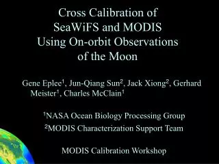
Vicarious calibration of MODIS to SeaWiFS: • Rayleigh, foam, glint can be modeled • Aerosol radiances from NIR bands using standard calibration • Water-leaving radiances from SeaWiFS level 3 data Where do we get the true radiance from ? LTOA = [ Lrayleigh + Laerosol + tLfoam + TLglint + tdLw ] · tg (T, t, td, tg: transmittances )
Optimization process Lm: MODIS measured TOA radiance (without polarization corr.) LTOA: modeled (nLw from SeaWiFS, aerosols from MODIS NIR bands) Q, U: Stokes vector parameters (modeled from Rayleigh) Lm = M11LTOA + M12Q + M13U • find best M11, M12, M13 per band, detector, and mirror-side • M11, M12, M13 = f (scan angle), cubic (M11) and linear (M12) • do this for one day per month over the mission lifespan • optimize over global distribution of path geometries
M11: MODIS Terra blue band temporal trends Mirror side 1 Mirror side 2 RVS = 1/M11 412 Detector 4 443 Space View (lunar) frame Nadir frame Solar Diffuser frame 488
M12: MODIS Terrablue band temporal trends Mirror side 1 Mirror side 2 M12 acts on the Q component 412 Detector 4 443 Space View (lunar) frame Nadir frame Solar Diffuser frame 488
Blue band RVS & polarization sensitivity MS1, Detector 4 M13 fixed to pre-launch 412 443 488
MODIS Terra and Aqua comparison Terra MS2, Detector 4 Aqua MS2, Detector 4 1/M11 M12 M13 1/M11 M12 M13 412 443 488 531 551 667 678
Detector polarization dependency prelaunch and on-orbit: band 12
Detector polarization dependency prelaunch and on-orbit: band 8
Comparison of Terra M11 from vicarious calibration to SeaWiFS for 3 view angles lunar detector residuals and Aqua operational corr. Black, blue, red line: Terra M11 for -45deg,0deg,+45deg Black (green) triangles: lunar residuals for Terra (Aqua) Green diamonds: operational Aqua detector corrections
Aqua M11 from vicarious calibration to SeaWiFS for 3 view angles Black, blue, red line: Terra M11 for -45deg,0deg,+45deg Dashed lines: +/- 0.1%
Conclusions • Detector dependency of MODIS prelaunch polarization characterization is suspect • Vicarious calibration of MODIS to SeaWiFS shows very small variation of polarization sensitivity for detectors, opposite to prelaunch results for bands 10-13 (~1% variation) • For bands 8 and 9, there is good agreement • For the first four years on-orbit, MODIS Terra and Aqua need constant offsets to calibration coefficients m1 (detector 1 too high, detector 10 too low, ~1% variation) • These offsets do not vary with scan angle
Blue band RVS & polarization sensitivity MS2 M13 fixed to pre-launch 412 443 488 Detector 4