Download
1 / 35
350 likes | 452 Views
VERA project. H.Kobayashi NAOJ,VERA project VLBA 10 th Anniversary Conference (Socorro, June 12, 2003). Project members. 13 scientists (NAOJ, Kagoshima Univ.)

E N D
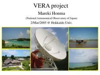
VERAproject H.Kobayashi NAOJ,VERA project VLBA 10th Anniversary Conference (Socorro, June 12, 2003)
Project members • 13 scientists (NAOJ, Kagoshima Univ.) • H.Kobayashi, S.Manabe, N.Kawaguchi, T.Omodaka, K.Shibata, O.Kameya, Y.Tamura, M.Honma, K.Hirota, Y.Kanya, T.Jike, H. Ishituka, M.Rijoha • 7 technicians • T.Miyaji, K.Horiai, S.Kuji, K.Iwadate, K.Satou, H.Sakai, T.Bushimata • 8 graduate students • T.Oyama, T.Kurayama, R.Kamohara, H.Suda, S.Sakakibara, K.Nakashima, R.Shimizu, Y.Che
Scientific goal • Astrometry with 10μarcsec. accuracy between background object and galactic object within 2.2 degree separation • Proper motion and parallax measurements • 3D map and velocity field of the Galaxy • Detailed 3D velocity structure of molecular gas around evolved stars and star forming regions • Phase referencing to improve sensitivity with long integration
Expected distance accuracy of VERA Sun 10% error at the G.C 20% error at opposite side
Specifications • Antenna diameter ; 20m • Observing bands ; 2GHz, 8GHz, 22GHz、43GHz • Tape recording rate ; 1Gbps • 2 beam system for phase referencing • Path error between 2 beam; 100μm
Construction of the antenna • Panel adjustment • Surface accuracy • 0.15mm rms • Panel; 0.1 mm rms • Panel adjustment; 0.1 mm rms • Sub ref.: 0.03mm rms
Cooled HEMT receiver Trx = 60 K @ 22GHz 40K@22GHz Trx=130K @43GHz 70K@43GHz Discrete HEMT MMIC HEMT
Radiator on the antenna surface • Noise source on the dish • Symmetric distribution of 4 noise sources • Instrumental phase error is estimated by the average of 4.
Instrumentalphase correction • Phase difference of surface radiator between 2 beams • Less than 1degreemeasurement accuracy is achieved 2B phase response from surface radiator depend on beam separation
First phase variations between 2 beams Fringe phase of W49N,OH43 and difference Allan variance of them
Coherence improvement Coherence drop of 1B and 2B fringe Fringe detection with 20 min. integration, GRB030329
Digital backend • 2.4Gbps transmit for each beam • Digital filter is used for frequency selection
Fringe detection by SX mode Nov. 19th, 2002 between VERA mizusawa- Gifu
Geodesy observations • Combine with the world coordinate by SX observations • Combined with Tsukuba 32m of Japanese GSI • Baseline determination • Required accuracy2mm • 22GHz wideband observations • SX conventional observations
VERA first fringe on Feb. 20th, 2002 Orion-KL H2O maser
1Gbps recorder & correlation • SONYDIR20001024Mbps • 80 min/tape • Mitaka FX correlator • 5 station correlation with 1Gbps • Output to CODA system • Convert correlation data to FITS
First 1Gbps fringe among VERA 4 stations, Sep. 18th, 2002 IrーIs OgーIs Mz-Is Mz-Ir
Test observations • Phase referencing check • 22GHz • SgrB2-SgrA*, W51N, W49N, Orion-KL, W3OH • VX-Sgr, VY-CMa, etc • 43GHz • Orion-KL • Fringe check and calibrators • Strong H2O masers (>20Jy), • Calibrator candidates
Expected sensitivity 1 * Measured value
VERA Mizusawa met a strong earthquake (Sanriku-minami jishin) Vertical 0.2G, Horizontal 0.3G
Plan of VERA 2002: Fringedetection / 2B fringe test 2003: Feasibility check of 2B interferometer Test observations for astrometry 2004: Test observations for astrometry Improvement of system sensitivity 2005: Complete
VERA & KVN Network Mizusawa KVN VERA Iriki Ogasawara Ishigakijima
16 VLBI stations in east Asia Under operation Under construction