Download
1 / 31
310 likes | 323 Views
WEAK MAGNETIC FIELD MEASUREMENT SYSTEM. Andrés G. Delannoy - 14949N SIST Program University of Puerto Rico at Mayagüez Fermi National Accelerator Laboratory August 5, 2008. A genda. Introduction Hall Probe Magnetic Measurement System Lock-In Amplifier LabVIEW Simulations

E N D
WEAK MAGNETIC FIELD MEASUREMENT SYSTEM Andrés G. Delannoy - 14949N SIST Program University of Puerto Rico at Mayagüez Fermi National Accelerator Laboratory August 5, 2008
Agenda • Introduction • Hall Probe • Magnetic Measurement System • Lock-In Amplifier • LabVIEW Simulations • Lo-Pass & Curve Fitting Models • Results • Data Acquisition & Results • DC Probe Excitation • AC Probe Excitation • Probe Frequency Response • Summary & Conclusions • Future Work
Introduction Hall Probe Magnetic Measurement System Lock-In Amplifier
Introduction • HINS 8GeV linear accelerator R&D project • 7.2T @ 250A superconducting focusing magnets • Very low stray field (<0.10 G) requirement proximate to solenoid • Signal must be recovered from electromagnetic noise • Magnetic field measurement necessary at 300K and 4K
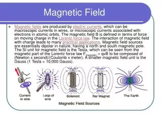
Hall probe • Current through a Hall probe responds to external magnetic field by generating voltage. • The measured voltage is proportional to the magnetic field. V+ Copper winding (2 turns) i B Current Source V- I+ Reference Signal I-
Magnetic measurement system • Setup: • Circular coil with two turns generating 0.201 G/A • Two probes in axis of coil • Cryomagnetics model HSP-T • Sensitivity > 1 mV/G • Nested magnetic shield • Probe excitation methods: • DC • AC • Measurement goals (0.01 G): • Probe Sensitivity (mV/G) • Noise Level (G)
Coil’s Magnetic Field Calculation Biot and Savart Law: At 1A and 12.5cm coil circumference
Lock-In Amplifier Signal Recovery Method
Lock-In Amplifier • Recovers a periodic signal from a noisy environment • Mixes the noisy signal with a reference signal of the same frequency • Applies Low-Pass Filter to rectified signal
LabView Simulations Lo-Pass & Curve Fitting Models Results
LabView Simulation • Laboratory Virtual Instrumentation Engineering Workbench • Graphical programming language (named G) • Used for data acquisition, instrument control, and industrial automation • Based on Virtual Instruments (VI)
Lock-In Simulation:Results • Model approaches: • Chopper + Lo-Pass Model • Full Wave Rectifier + Lo-Pass Model • Fourier Transform Model • Curve-Fitting Model • The modeled filters recovered the simulated signal’s amplitude with 5-10% error (for 1:1 SNR). • A much higher level of certainty is required for our magnetic measurement system.
Data Acquisition DC Probe Excitation AC Probe Excitation
Data Acquisition:Power Supply & Preamp/Filter • SRS Module • SIM 911 BJT Preamp • SIM 965 Analog Filter • HP E3610A • Coil Current Source • Keithley 2400 • DC Probe Current Source
Data Acquisition:Signal Recovery 7265 • DSP Lock-In Amplifier
Data Acquisition: PXI • PCI eXtensions for Instrumentation (PXI) is a modular instrumentation platform used as a basis for building electronic test equipment or automation systems.
DATA ACQUISITION: Data Recording • GPIB Connector & Analog Voltage Output readings were recorded using the NI interface. • Various LabView programs were written to record these data to file.
DATA ACQUISITION: DC Probe Excitation- Sensitivity Probe 1 DC sensitivity ΔV/ΔB = 9.1289 V/G Probe Direct Current Source Low Noise Pre-Amp Coil Direct Current Source Hall Probe Low-Pass Filter Probe 2 DC sensitivity ΔV/ΔB = 6.4051 V/G LabVIEW Voltage Measurement
DATA ACQUISITION:DC Probe Excitation - Noise Level • Probe 1 Noise Level • Probe 2 Noise Level
DATA ACQUISITION:AC Probe Excitation - Sensitivity & Noise Level • Probe 1 Noise Level vs. Frequency • Probe 2 Noise Level vs. Frequency
DATA ACQUISITION:AC Frequency Response - Probe 1 & 2 LabVIEW Voltage Measurement Lock-In Amplifier Lock-In Amplifier Input Probe Direct Current Source 10:1 Transformer Hall Probe
DATA ACQUISITION:Transformer Noise Level vs. Frequency LabVIEW Voltage Measurement Lock-In Amplifier Lock-In Amplifier Input Probe Direct Current Source 10:1 Transformer Lock-In Voltage Without Transformer is Constant with Frequency
Coil Current Source Noise Level Coil Direct Current Source LabVIEW Voltage Measurement 1.1W Shunt Resistor Coil Current Supply contributes 0.00006 G to the noise level
Summary & Conclusions • Software based signal recovery results are inappropriate for the certainty required • Hall Probe sensitivity depends on excitation current (AC vs. DC). • Probe’s 1 & 2 sensitivity dissimilarity may be due to geometric or manufacturing inconsistencies • Lock-In amplifier offers lower noise figures, DC excitation must implement lo-pass filter. • Noise level may be further reduced by using higher precision equipment (power supplies, transformers, etc.)
Future Work • Calculate the change in magnetic field as probe is moved off-center • Detailed noise level analysis at wider range of frequencies for AC probe excitation • Shielding method & effectiveness • Cryogenic temperature measurements
Acknowledgements • Michael A. Tartaglia • Dmitri A. Sergatskov • Magnet Systems Department
References • Griffiths, David J. Introduction to Electrodynamics. 3rd ed. New Jersey: John Wiley & Sons, 1999 p.215-218. • Reitz, John R., and Frederick J. Milford. Foundations of Electromagnetic Theory. London: Addison Wesley, 1960 p.149-159. • Jackson, John D. Classical Electrodynamics. 3rd ed. California: John Wiley & Sons, 1999 p.174-178. • R. Carcagno, et al. Superconducting Solenoid Magnet Test Results. ASC-06, Seattle, 2006. • I. Terechkine, et al. Focusing Solenoid for the Front End of a Linear RF Accelerator. PAQ-07, Albuquerque, 2007. • R. Carcagno, et al. Test Solenoids: Expected Performance and Test Results. TD-06-027, TD-06-028, TD-06-029, FNAL, July 2006.
Questions The Answer to Life, the Universe, and Everything