Download
1 / 14
140 likes | 294 Views
Passive damping systems for floating vertical axis wind turbines 3 rd February, 2013 Michael Borg, Cranfield University. Outline. Introduction Passive damping systems Evaluation & Selection Response analysis Application to a floating VAWT Conclusions. Introduction.

E N D
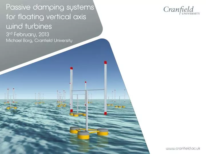
Passive damping systems for floating vertical axis wind turbines3rd February, 2013Michael Borg, Cranfield University
Outline • Introduction • Passive damping systems • Evaluation & Selection • Response analysis • Application to a floating VAWT • Conclusions
Introduction • Need of floating foundations for far offshore wind farms • One possible solution: Greater induced loads Turbulent winds Turbine control Reduced aerodynamic performance Structure flexibility Waves & Currents Mooring lines Damping devices Passive Active
Evaluation & Selection • Trifloaterstructure in Dogger Bank, North Sea • TOPSIS analysis • Mean motion reduction and variation coefficient • Cost • TRL • Weight vectors obtained from experience and survey Hs = 4.3m Tz = 10s
Evaluation & Selection • TOPSIS analysis results: √ √ √
Preliminary Designs • Heave Bottom Plates • Shift natural period > 20s • Plate diameter = 30m • Anti-Roll Tanks • Mass and Frequency Ratios • Open Bottom Tanks • Shift natural period -> modifying vessel stiffness • Sensitivity analysis on cost/mass and pitch stiffness
Dynamic Response Analysis • Heave Response Amplitude Operator
Dynamic Response Analysis • Roll Response Amplitude Operator
Application to a floating VAWT • 5MW H-type VAWT rotor with Trifloater • Time-domain analysis using MSS toolbox in MATLAB/Simulink • Decoupled aero-hydro dynamics model
Application to a floating VAWTModel basis Hydrodynamics • Time-domain Cummins’ equation • Radiation force state-space representation • Simulation ratios of 21:1 Aerodynamics • Double Multiple Streamtube (DMST) model • Includes dynamic stall, tower shadow, tip ad junction losses Simulation Parameters • 3-hour simulation time • JONSWAP spectrum (Hs=4.3m, Tz=10s) • 1000 harmonic wave components • Power law vertical wind profile • Uhub = 15m/s • α = 0.11
Conclusions • Selection of most promising damping devices for a semi-submersible support structure. • Three optimal damping devices compared. • The designed damping devices have been applied to a floating VAWT.
Thank you Questions?