Download
1 / 11
110 likes | 120 Views
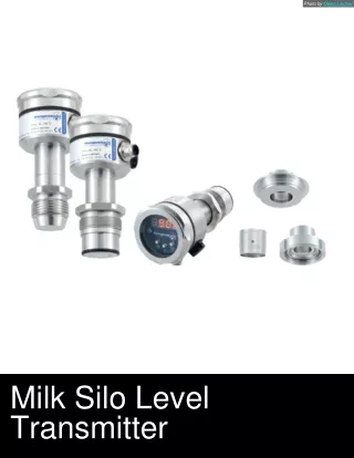
Trumen is one of Indiau2019s leading manufacturer, exporter supplier of Level Switches, Level Sensors, Level Indicators Level Transmitters in India, Indonesia,etc.<br>Trumen is a technocrat driven organization aimed at providing top-of-the-range and high quality level measurement and process control instruments. Formed by the pioneers who devoted their respective lives in development, design and delivery of solution to the problems faced in the field of level sensing and process measurements. Trumen has a fixed point agenda about "sensing matters", and each device created at Trumen is thoroughly test

E N D
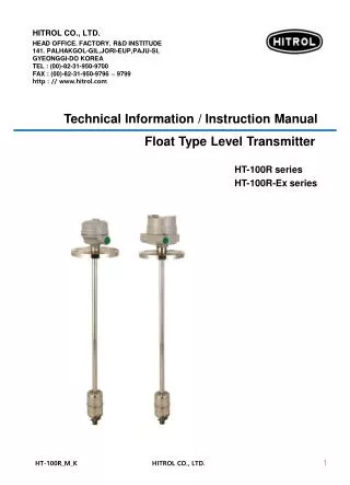
TLC: Capacitance Type Level Transmitter for Liquids ® sensing matters Instruction Manual Customer Support Phone: +91-731-656 2425 email: sales@trumen.in email: support@trumen.in web:www.trumen.in Trumen Technologies Pvt. Ltd. 39 Mangal Nagar, Behind Sai Ram Plaza, Near Rajiv Gandhi Circle, AB Road, Indore, MP 452 001, India Phone: +91-731-497 2065
Operating Principle The probe forms a capacitance with the metalic tank-wall. The capacitance is sum of three capacitance:- C(residual) C(air)=ε(air) x P x (H-L) C(material)=ε(material) x P x L C(residual) is due to device itself. C(material) Where ε(air) is the dielectric constant of air ≈1. ε(material) is dielectric constant of material. P is the constant of probe and installation, H is the active length of probe and L is the level of material. Capacitance to level translation is performed with the aid of on-site calibration also called "wet-calibration". The device stores a low level capacitance as level for 4mA and high level capacitance as level for 20mA as defined by the user. mA 4 20 CALIB read C(low) for 4mA Using these values and following equation L(high) C(high) C(low) L(low) L(high) L(low) = P x {ε(material) ε(air)} Level 4 mili-Ampere 20 device creates a chart of level to 4-20mA translation. mA 4 20 CALIB read C(high) for 20mA tlc2-manual-01 www.trumen.in Page 1
Introduction - TLC2 controls & indicators B A Process indicating LED status B Calibration & configuration switches C Connecting terminals D External Earthing Terminal A TLC2 1500pF Range turn-on to set 4200pF D ! status increase/Water decrease/damping 20mA/5V/10V (100%) 4mA/1V/2V (0%) 12 to 60 VDC 4..20mA o/p connection terminals U 1..5V 2..10V* *Min Supply U > 21.5V Vo C 1 2 3 4 5 6 7 8 9 1 + of DC of 4-20mA Loop 2 - of DC of 4-20mA Loop Supply: 12 to 60 VDC 3 Earth terminal for safety 4 Reference for 1 to 5V Output at terminal no.2 5 Reference for 2 to 10V Output at terminal no.2 6 to 9 Not Used configuration switches 1 4mA or 0% calibration switch: This switch calibrates 0% or 4mA level and it also trims 4.0mA value in association with switch 3 (decrease) and 4 (increase) TLC2 OFF Position 1500pF Range turn-on to set 2 20mA or 100% calibration switch: This switch calibrates 100% or 20mA level and it also trims 20.0mA value in association with switch 3 (decrease) and 4 (increase) 4200pF ON Position ! increase/Water decrease/damping 20mA/5V/10V (100%) 4mA/1V/2V (0%) 3 Digital Trim (decrease) Switch OFF Position ON Position 4 Digital Trim (increase) Switch Switch#4 also act as diagnostic switch 5 Range Switch select for 1500pF to 4200pF Example of Switch in On and Off Positions Shown on the left is typical ON and OFF positions of the DIP switches. Always use a small screw driver to turn ON/OFF the switches using pen and other method may damage the switches. Using small screw-driver tip to turn-ON and OFF tlc2-manual-02 www.trumen.in Page 2
Connection Diagrams - TLC2 1. Grounded Load TLC2 1500pF Range turn-on to set 4200pF ! increase/Water status decrease/damping 20mA/5V/10V (100%) 4mA/1V/2V (0%) 12 to 60 VDC 4..20mA o/p U 1..5V 2..10V* *Min Supply U > 21.5V Vo 1 2 3 4 5 6 7 8 9 mA Supply 12 to 60 VDC Connect to Earth for Safety Meter/Indicator/PLC/SCADA 2. Floating Load TLC2 1500pF Range turn-on to set 4200pF ! increase/Water status decrease/damping 20mA/5V/10V (100%) 4mA/1V/2V (0%) 12 to 60 VDC 4..20mA o/p U 1..5V 2..10V* *Min Supply U > 21.5V Vo mA 1 2 3 4 5 6 7 8 9 Supply 12 to 60 VDC Meter/Indicator/PLC/SCADA Connect to Earth for Safety 3. Voltage Output with Grounded Load TLC2 1500pF Range turn-on to set 4200pF ! increase/Water status decrease/damping 20mA/5V/10V (100%) 4mA/1V/2V (0%) 12 to 60 VDC 4..20mA o/p U 1..5V 2..10V* *Min Supply U > 21.5V Vo 1 2 3 4 5 6 7 8 9 Supply 12 to 60 VDC Voltage Output 100 Ohm (0.4 to 2V) 250 Ohm (1 to 5V) 500 Ohm (2 to 10V) Connect to Earth for Safety tlc2-manual-03 www.trumen.in Page 3
Full calibration (100% or 20mA Calibration) TLC2 TLC2 TLC2 1500pF Range 1500pF Range 1500pF Range turn-on turn-on turn-on to set to set to set 4200pF 4200pF 4200pF ! ! ! increase/Water increase/Water status status increase/Water status Calibrate 20mA for 100% Level decrease/damping 20mA/5V/10V (100%) 4mA/1V/2V (0%) decrease/damping 20mA/5V/10V (100%) 4mA/1V/2V (0%) decrease/damping 20mA/5V/10V (100%) 4mA/1V/2V (0%) 12 to 60 VDC 4..20mA o/p 12 to 60 VDC 4..20mA o/p 12 to 60 VDC 4..20mA o/p U U U 1..5V 2..10V* 1..5V 2..10V* 1..5V 2..10V* *Min Supply U > 21.5V *Min Supply U > 21.5V Vo Vo *Min Supply U > 21.5V Vo 1 2 3 4 5 6 7 8 9 1 2 3 4 5 6 7 8 9 1 2 3 4 5 6 7 8 9 1 1 1 2 2 2 3 4 3 4 3 4 5 5 5 status status LED must be blinking once per 2 sec (No Error). MiliAmmeter must be connected in series with the device Turn ON Switch# 2 Wait till mA meter shows 20mA. Turn-off switch# 2, 20mA level or 100% level is calibrated. LED will blink faster (not as faster as Error blink). During this time the switch can be put back if accidently turned ON. LED will start blinking three times then off, successively. mA meter will show 4mA 1 Make sure that switch 1, 3, 4 & 5 are OFF (as shown above). 2 3 4 Switches1,2,3 & 4 must be OFF (#5 is as per range). Fill the material to the desired level Trimming (100% or 20mA) Trimming can be done. If 20mA reading in mili-ammeter is lesser or more then 20mA. Use the trim-switches (switch# 3 to decrease, say 20.3 mA to 20.0) (switch# 4 to increase, say 19.7 mA to 20.0). For trimming 100% (20mA) a) Turn switch 3/4 (decrease/increase) ON b) Turn 20mA switch ON (this sequence is important). and watch the mili-ammeter till correct trimming of 20mA is done. Immediately a) Turn switch 3/4 (decrease/increase) OFF b) Turn 20mA switch OFF (sequentially). Trimming Trimming turn-on turn-on to set to set 4 mA 20 mA trim (decrease) trim (increase) 4 mA 20 mA trim (decrease) trim (increase) Empty calibration (0% or 4ma Calibration) TLC2 TLC2 TLC2 1500pF Range 1500pF Range 1500pF Range turn-on turn-on turn-on to set to set to set 4200pF 4200pF 4200pF ! ! ! increase/Water increase/Water increase/Water status status status decrease/damping 20mA/5V/10V (100%) 4mA/1V/2V (0%) decrease/damping 20mA/5V/10V (100%) 4mA/1V/2V (0%) decrease/damping 20mA/5V/10V (100%) 4mA/1V/2V (0%) Calibrate 4mA for 0% Level 12 to 60 VDC 4..20mA o/p 12 to 60 VDC 4..20mA o/p 12 to 60 VDC 4..20mA o/p U U U 1..5V 2..10V* 1..5V 2..10V* 1..5V 2..10V* *Min Supply U > 21.5V *Min Supply U > 21.5V *Min Supply U > 21.5V Vo Vo Vo 1 2 3 4 5 6 7 8 9 1 2 3 4 5 6 7 8 9 1 2 3 4 5 6 7 8 9 1 1 1 2 2 2 3 4 3 4 3 4 5 5 5 status status LED must be blinking once per 2 sec (No Error). MiliAmmeter must be connected in series with the device Turn ON Switch# 1 LED will blink faster (not as faster as Error blink). During this time the switch can be put back if accidently turned ON. LED will start blinking three times then off, successively. mA meter will show 20mA Wait till mA meter shows 4mA. Turn-off switch# 1, 4mA level or 0% level is calibrated. 1 2 3 4 Make sure that switch 2, 3, 4 & 5 are OFF (as shown above) 5 Switches1,2,3 & 4 must be OFF (#5 is as per range). Empty the material to the desired level. Trimming (0% or 4mA) For trimming 0% (4mA) a) Turn switch 3/4 (decrease/increase) ON b) Turn 4mA switch ON (this sequence is important). and watch the mili-ammeter till correct trimming of 4mA is done. Immediately a) Turn switch 3/4 (decrease/increase) OFF b) Turn 4mA switch OFF (sequentially). Trimming can be done. If 4mA reading in mili-ammeter is lesser or more than 4mA Use the trim-switches (switch# 3 to decrease, say 4.1 mA to 4.0) (switch# 4 to increase, say 3.7 mA to 4.0) Trimming Trimming turn-on turn-on to set to set 4 mA 20 mA trim (decrease) trim (increase) 4 mA 20 mA trim (decrease) trim (increase) Damping(response time) 1. Turn switch 3 ON (switch no. 1, 2 & 4 should be off) 2. LED will blink rapidly, then it will turn OFF. 3. Once LED is OFF, turn switch 1 ON, LED will turn ON. 4. Turn switch 1 OFF, LED will turn OFF. damping is set to 1 sec. 5. Repeat operation 3 and 4 for as many seconds of damping required, to finish seting, turn all switches OFF. tlc2-manual-04 1 1 2 2 3 4 3 4 5 5 Turn switch 3 ON Turn switch 1 ON Page 4 www.trumen.in
Operation Matrix - TLC2 This model is best suitable for continuous current level measurement. Material & Installation Switching Operation Calibration Switches Current Output and LED indication When the material in tank is at 100%. All switches are OFF. LED will blink faster mA meter will show 4mA. Wait till mA meter shows 20mA. 20mA or 100% Level ON 1 2 3 4 LED will blink faster 4 mA 20 mA trim (decrease) trim (increase) Current meter shows 20mA. When the material in tank is at 0%. All switches are OFF. LED will blink faster mA meter will show 20mA. Wait till mA meter shows 4mA. LED will blink faster ON 1 2 3 4 4mA or 0% Level 4 mA 20 mA trim (decrease) trim (increase) Current meter shows 4mA. Page 5 www.trumen.in tlc2-manual-05
Power Supply electrical connections TLC2 DC Supply min. 12V max. 60V Not used electrical connections TLC2-(1-5V) Voltage Output Not used DC Supply min. 12V max. 60V Voltage output on terminals 2,4 Voltmeter/Analog input resistance should be more than 10K-Ohm electrical connections TLC2-(2-10V) Voltage Output Not used DC Supply min. 12V max. 60V Voltage output on terminals 2,5 Voltmeter/Analog input resistance should be more than 10K-Ohm Proper connection to supply earth terminal (3) and the external earth terminal (screw) is must. tlc2-manual-06 www.trumen.in Page 6
Status LED Indications 1. Blinking once per two seconds : No Error 2. Blinking rapidly rapidly : Too High Capacitance at probe TLC2 TLC2 1500pF Range 1500pF Range turn-on turn-on to set to set 4200pF 4200pF status ! ! increase/Water increase/Water status status decrease/damping 20mA/5V/10V (100%) 4mA/1V/2V (0%) decrease/damping 20mA/5V/10V (100%) 4mA/1V/2V (0%) 12 to 60 VDC 4..20mA o/p 12 to 60 VDC 4..20mA o/p U U 1..5V 2..10V* 1..5V 2..10V* *Min Supply U > 21.5V *Min Supply U > 21.5V Vo Vo 1 2 3 4 5 6 7 8 9 1 2 3 4 5 6 7 8 9 status C(residual) C(material) High Capacitance at probe 3. Due to Probe insulation failure in conductive liquid 5. change the range from 1500pF to 4200pF using switch# 5 4. Probe too long for TLC2 device in conductive liquid. 1500pF Range 1 2 3 4 5 1 2 3 4 5 4200pF ! increase/Water decrease/damping 20mA/5V/10V (100%) 4mA/1V/2V (0%) Probe is too long Error is indicated by 21mA on output. Page 7 www.trumen.in tlc2-manual-07
Technical Specification Features Specifications 1. Fast Switching Response EIL Supply Output Loop Resistance Integral Electronics Two-wire Loop Powered 15-60 VDC 4-20mA Loop powered, Error output 21mA maximum 475 Ohm @ 24VDC supply 2. High temperature endurable probes 3. Single sensor allows pump-control & multi-point switching 4. Easy calibration with or without material EIV Supply Output Integral Electronics Three/Four wire (negative common) 15-60 VDC Field Configurable : 0% => 0V/1V (2V for 100%=>10V), 100% => 5V/10V minimum 10K Ohm 5. Remote electronics with std 10 meters cable length 6. External indication LED available 7. Threaded , Flanged Mountings & TC Load Resistance 8. Electronic Inserts support all requirements 9. Ingress protection : IP 68/65 (as per IS-13947) EIM Supply Interface/Output Integral Electronics Three/Four wire (negative common) 15-60 VDC ModBus-RTU / complementry 0-5V output suitable for > 20K Ohm Calibration/configuration available through ModBus as well as without using DIP switches 10. Ex-proof (Ex d T6 IP-66 IIC) - Flameproof as per IS/IEC 60079-1:2007 - Weatherproof (IP-66) as per IS/IEC 60529:2001 - Suitable for Gas Group : IIC - Suitable for Zone 1 & 2 atmospheres 12. Compact size ICT specifications ICT provides numerical LED indicator, control logic with relay outputs and re-transmission over galvanically isolated 4-20mA output 13. Rigid rod / flexible rope versions 14. No potentiometers - hassle free calibration compensation against material build-up ICT Power Supply SA : 80-260VAC, 50/60Hz for AC version SD : 16 to 32VDC for DC version Applications ICT RSx Relay Rating SPDT 5 A each @ 24VDC or 220VAC (3 SPDT relays in IP65, max 6 SPDT relays in IP40 metal sheet enclosure) 1. Free flowing homogeneous liquids like oil, raw water, WFI, DM/DI water etc 2. Suitable for top mounting ICT RKx Relay Rating Contactors with 2NO/2NC rated at (1, 2 or 3 contactors, only in IP40 metal sheet enclosure) 3. Process temperature max. 200°C 4. Process pressure max. 20 bar ICT Isolated Loop Supply 24V +/- 4V Suitable for maximum 25mA load ICT re-Transmission 4-20mA, Error@21mA, galvanically isolated loop powered section for use with either integrated ICT Isolated Loop Supply or any external DC supply within range 16 to 50VDC Typical Mountings ICT remote indicator-controller using two-core-shielded pvc cable (1...1.5 mm2 conductors) Shileded 2 Core PVC cable with 1 to 1.5 mm2 conductors cross section ICT to TLC cable Min. Dielectric Constant 1.8 (non-hygroscopic) Ambient Temp. -20°C ... 70°C (-4°F ... 158 °F) inactive length Process Temp. -20°C ... 100°C (-4°F ... 212 °F) (ground) stilling well tube, flanged mounting Extended Process Temperature PTFE Insulation: -30 °C ... 250 °C (-22 °F ... 482 °F) Ceramic Insulation: -30 °C ... 600 °C (-22°F ... 1,112 °F) (extensions & heat sinks required) PTFE insulated/bare rope Process Pressure absolute / max. 15 bar (for ceramic insulation : 1 atm) active length (sensitive) Wetted Parts SS-304, SS-316, SS-316L, PTFE, part ceramic Process Connection TC / NPT / BSP 1", 1¼", 1½", 2" etc Flanged : ANSI/JIS/DIN/ASA/custom Probe Insertion Length: Rigid Rod : 50mm to 3,000mm Flexible Rope : 100mm to 20,000mm Specifications are subject to change without prior notice tlc2-manual-08 www.trumen.in Page 8
Do's and Don'ts Features Installation Precaution 1. Always connect the "Earth" to the external "Earthing" screw 1 3 2. Tighten the cable entries & glands properly 2 3. Secure the top aluminium cover at its place properly once the electrical connections and other settings are completed 4. Always tighten the process connection using proper wrench never try to tight by rotating the aluminium housing 4 5 5. Make sure process connection is same as that in hopper/tank 6 6. Transmitter probe should never be:- 6.1 Bent 6.2 Held from thin part 6.3 Cut or machined in any way 6.4 Extended by welding or machining 7 7. Airvent hole should be clear from material and other dust particles 8. Nozzles should never be longer than the probe 9. Never climb either by gripping or stepping over either the probe or its aluminium housing 10. Obeserve other safety precautions as required at the place of application tlc-manual-09 www.trumen.in Page 9
Troubleshooting Indication Probable cause Work-around Solution Sensor electronic insert is needed to be replaced. All LEDs are OFF Power section of sensor electronic insert is failed Even proper voltage is avialable Recalibrate at different level or replace the probe if shorted. After calibration current meter showing 21mA and first three LEDs are glowing dim Sense and earth part of probe are shorted Check if probe sense part are shorted with ground / PTFE insulation is break and conductive liquid are entered into it Wrong calibration done at same level Calibration and settings are all OK but mA reading abruptly change or chatters continuously Power supply carrying extra noise and capacitance amplifier picking the noise Make necessary arrangements to filter the noise in power-line before being fed to the device Device contains sufficient filtering of power supply noise inside, but sometimes external earth is needed to make filters sink the extra power supply noise back to earth, connect proper ground. Ground is not properly connected Provide an exclusive earthing to terminal# 3, capacitance enclosure earthing screw and capacitance probe process connection (device mounting screw or flange) Maintenance and Spares Shown on the left are various parts of TLC capacitance level switch. Separatable parts are Top Cover Electronic Insert connection terminals electronic insert fixing screw 1. Electronic insert in short called 'electronics' 2. Probe + Enclosure + Cover + Glands collectively called 'mechanical' 4-way male connector for sensor (probe) 4-way female connector from sensor (probe) For maintenance issues involving replacement of 'electronics', just a single fixing screw is needed to be released. Device enclosure Cable glands Lift the electronics slowly by holding electronics with one hand and mechanical with other, as wires are connected using rigid 4-way connectors to it. Thermal spacer (where needed) Disconnect 4-way connector by holding electronics with one hand and female of connector by other hand, while the rest of the device is at rest. Process connection Connect the new replaced sensor. 4-way connector is unidirectional and only connects in proper direction. Set the electronics properly to its position. Match the mounting screw hole of electronics with that of enclosure and fix the screw. Stilling well tube For mechanical issues please send the entire device back to Trumen. tlc-manual-10 www.trumen.in Page 10