Download
1 / 11
110 likes | 115 Views
Understand the OSI model and its 7 layers, including the Application, Presentation, Session, Transport, Network, Data Link, and Physical layers. Learn about protocols like TCP and UDP.

E N D
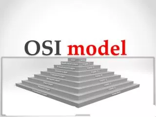
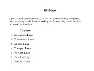
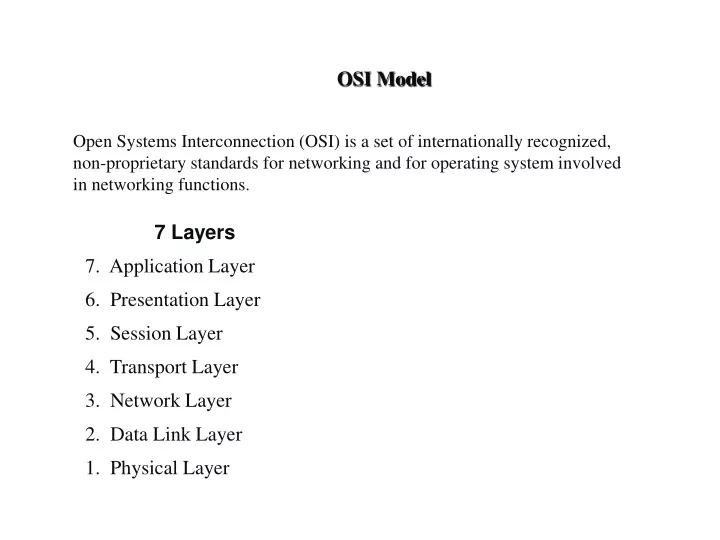
OSI Model Open Systems Interconnection (OSI) is a set of internationally recognized, non-proprietary standards for networking and for operating system involved in networking functions. 7 Layers 7. Application Layer 6. Presentation Layer 5. Session Layer 4. Transport Layer 3. Network Layer 2. Data Link Layer 1. Physical Layer
LAYER 7 – The APPLICATION Layer • The top layer of the OSI model • Provides a set of interfaces for sending and receiving applications and to use network services, such as: message handling and database query processing • Responsibility: The application layer is responsible for providing services to the user.
LAYER 6 – The PRESENTATION Layer • Manages data-format information for networked communications (the network’s translator) • For outgoing messages, it converts data into a generic format for network transmission; for incoming messages, it converts data from the generic network format to a format that the receiving application can understand • This layer is also responsible for certain protocol conversions, data encryption/decryption, or data compression/decompression • A special software facility called a “redirector” operates at this layer to determine if a request is network related on not and forward network-related requests to an appropriate network resource
LAYER 5 – The SESSION Layer • Enables two networked resources to hold ongoing communications (called a session) across a network • Applications on either end of the session are able to ex hange data for the duration of the session This layer is: • Responsible for initiating, maintaining and terminating sessions • Responsible for security and access control to session information (via session participant identification) • Responsible for synchronization services, and for checkpoint services
LAYER 4 – The TRANSPORT Layer • Manages the transmission of data across a network • Manages the flow of data between parties by segmenting long data streams into smaller data chunks (based on allowed “packet” size for a given transmission medium) • Reassembles chunks into their original sequence at the receiving end • Provides acknowledgements of successful transmissions and requests resends for packets which arrive with errors • The transport layer is responsible for the delivery of a message from one process to another.
LAYER 3 – The NETWORK Layer • Handles addressing messages for delivery, as well as translating logical network addresses and names into their physical counterparts • Responsible for deciding how to route transmissions between computers • This layer also handles the decisions needed to get data from one point to the next point along a network path • This layer also handles packet switching and network congestion control
LAYER 2 – The DATA LINK Layer • Handles special data frames (packets) between the Network layer and the Physical layer • At the receiving end, this layer packages raw data from the physical layer into data frames for delivery to the Network layer • At the sending end this layer handles conversion of data into raw formats that can be handled by the Physical Layer
LAYER 1 – The PHYSICAL Layer • Converts bits into electronic signals for outgoing messages • Converts electronic signals into bits for incoming messages • This layer manages the interface between the the computer and the network medium (coax, twisted pair, etc.) • This layer tells the driver software for the MAU (media attachment unit, ex. network interface cards (NICs, modems, etc.)) what needs to be sent across the medium • The bottom layer of the OSI model • The physical layer is responsible for movements of • individual bits from one hop (node) to the next.
What is a protocol? • A protocol is a collection of rules and procedures for two computers to exchange information • Protocol also defines the format of data that is being exchanged
TCP and UDP TCP – Transmission Control Protocol • TCP is a connection-oriented protocol • Does not mean it has a physical connection between sender and receiver • TCP provides the function to allow a connection virtually exists – also called virtual circuit • TCP provides the functions: • Dividing a chunk of data into segments • Reassembly segments into the original chunk • Provide further the functions such as reordering and data resend • Offering a reliable byte-stream delivery service