Download
1 / 27
270 likes | 486 Views
3 Element Beam Comparisons. Hey! Aren’t all antennas the same-o same-o perfectly designed. By Wb6dco Joe Perry jr. What to show about nothing!. The problem to solve is how to make a perfect 3 element beam. These are 3 element MONO Band beams. Make them perfect in every way.

E N D
3 Element Beam Comparisons Hey! Aren’t all antennas the same-o same-o perfectly designed. By Wb6dco Joe Perry jr
What to show about nothing! • The problem to solve is how to make a perfect 3 element beam. • These are 3 element MONO Band beams. • Make them perfect in every way. • Then we will combine them all into one not so perfect beam of many elements.
Beam Elements Calculated by WA7RAI Software • His software has auto mode, auto gain, or optimized gain or maximum forward gain. • We will use the auto-auto-optimized analysis for these beams. • Following are the element dimensions and spacing charts.
14.1 MHz translated to Inches • Reflector Half Length 209.4” • Reflector Spacing to Driven 167.53” • Driven Half Length 204.36” • Driven Spacing to Director 125.64” • Director Half Length 193.14”
28.2 MHz Dimension in Inches • Reflector Half Length 104.7” • Reflector Spacing to Driven 83.76” • Driven Half Length 102.18” • Driven Spacing to Director 62.82” • Director Half Length 96.54”
50.1 MHz Dimensions in Inches • Reflector Half Length 58.93” • Reflector Spacing to Driven 47.04” • Driven Half Length 57.48” • Driven Spacing to Director 35.28” • Director Half Length 54.3”
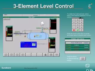
3 Element Mono Bands • Here are the EZNEC demo outputs for some beams • 14.1 mhz 11 gain 26 B/F • 28.2 mhz 13 gain 21 B/F • 50.1 mhz 11 gain 9 B/F • These represent standard 3 element beam design
Change the Reflector Length to 209” per side to see this effects the 28.2 MHz beam. Appears that the 28.2 beam with the longer Reflector does not change that much. 12 dBi down to 11 dBi.
28.2 MHz with 104.7” (left picture) and then 209” (right picture) Reflector half sides Using the 14.1 MHz beam reflector of 209” half wavelength, only changes the 28.2 MHz beam slightly. So, we can move the 28.2 elements onto the 14.1 MHz beam boom and see if both still work.
Merge 14.1 MHz and 28.2 MHz Elements on one beam boom. Drive the 28.2 MHz Driven Element and see if it still works. The 28.2 MHz beam still works great with the added other elements.
Now test if the 14.1 MHz beam will still propagate with the smaller 28.2 MHz beam elements sitting on the same boom. The left plot looking down on the original 14.1 MHz beam with only 3 elements, and the right plot is looking down with merged 20m and 10m beam elements. Note the main Gain goes down but is still usable good.
The launch angle changes from 36 deg’s down to 33 deg’s. The merged 20m Elements and the 10m Elements seem to work together and not destroy the propagation.
This is great, we can build a 3 element 20m beam and a 10m beam and stick them on the same boom pole. We use the 20m Reflector element for both 20m and 10m beams. The beam is tested at 300” (25 feet) above the ground. The 10m Beam The 20m beam Total length of the boom is about 300” or 25’.
Try putting the 10m beam out front of the 20m beam elements using the Director as the 10m Reflector. What will that do, besides make the boom longer. 10m inside 10m out front
10m elements out front of the 20m elements. Test what the 20m excited beam does not. This looks pretty good. The SWR’s are good also.
Can we merger MORE on the Boom. Like put the 50.1 MHz elements on the boom using one of the other elements as the reflector? If we look at the lengths of the elements on the new beam, they go from 209” down to 96”. So, the reflector element of the 50.1 MHz beam is 58.93” on one ½ side. So 2 * 58.93 = 117.86” Which of our elements are at least 118” long? The Director of the 14.1 MHz beam is 193”.. So, we will try and use the 193” as a reflector for 6meter band.
Now merge on to the beam the 6 meter band 50.1 Mhz elements. We excite the 14.1 MHz elements first.
Oky for a final we test the 50.1 MHz elements in excitement. This has some exciting parts. Lobes at 36 and 11 degrees forward and backwards. So this may get around the sky pretty well.
Conclusions • I don’t have any hi hi.. • It appears I can modify my 5 Wire beam now to hold more wires on the front end for 10m and 6m. • This will still point directly East but the lobs from the 3 sets of wires do not seem to ruin each other in SWR or pattern. • IT MIGHT WORK. Joe wb6dco