Download
1 / 22
220 likes | 223 Views
This lecture covers the concepts and operations of floating point arithmetic and digital design, including representation, addition, multiplication, MIPS instructions, fixed point arithmetic, subword parallelism, and basics of Boolean functions and logic blocks.

E N D
Lecture 10: Floating Point, Digital Design • Today’s topics: • FP arithmetic • Intro to Boolean functions
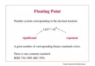
Examples Final representation: (-1)S x (1 + Fraction) x 2(Exponent – Bias) • Represent -0.75ten in single and double-precision formats Single: (1 + 8 + 23) Double: (1 + 11 + 52) • What decimal number is represented by the following single-precision number? 1 1000 0001 01000…0000
Examples Final representation: (-1)S x (1 + Fraction) x 2(Exponent – Bias) • Represent -0.75ten in single and double-precision formats Single: (1 + 8 + 23) 1 0111 1110 1000…000 Double: (1 + 11 + 52) 1 0111 1111 110 1000…000 • What decimal number is represented by the following single-precision number? 1 1000 0001 01000…0000 -5.0
FP Addition • Consider the following decimal example (can maintain only 4 decimal digits and 2 exponent digits) 9.999 x 101 + 1.610 x 10⁻¹ Convert to the larger exponent: 9.999 x 101 + 0.016 x 101 Add 10.015 x 101 Normalize 1.0015 x 10² Check for overflow/underflow Round 1.002 x 10² Re-normalize
FP Addition • Consider the following decimal example (can maintain only 4 decimal digits and 2 exponent digits) 9.999 x 101 + 1.610 x 10⁻¹ Convert to the larger exponent: 9.999 x 101 + 0.016 x 101 Add 10.015 x 101 Normalize 1.0015 x 10² Check for overflow/underflow Round 1.002 x 10² Re-normalize If we had more fraction bits, these errors would be minimized
FP Multiplication • Similar steps: • Compute exponent (careful!) • Multiply significands (set the binary point correctly) • Normalize • Round (potentially re-normalize) • Assign sign
MIPS Instructions • The usual add.s, add.d, sub, mul, div • Comparison instructions: c.eq.s, c.neq.s, c.lt.s…. These comparisons set an internal bit in hardware that is then inspected by branch instructions: bc1t, bc1f • Separate register file $f0 - $f31 : a double-precision value is stored in (say) $f4-$f5 and is referred to by $f4 • Load/store instructions (lwc1, swc1) must still use integer registers for address computation
Code Example float f2c (float fahr) { return ((5.0/9.0) * (fahr – 32.0)); } (argument fahr is stored in $f12) lwc1 $f16, const5 lwc1 $f18, const9 div.s $f16, $f16, $f18 lwc1 $f18, const32 sub.s $f18, $f12, $f18 mul.s $f0, $f16, $f18 jr $ra
Fixed Point • FP operations are much slower than integer ops • Fixed point arithmetic uses integers, but assumes that every number is multiplied by the same factor • Example: with a factor of 1/1000, the fixed-point representations for 1.46, 1.7198, and 5624 are respectively 1460, 1720, and 5624000 • More programming effort and possibly lower precision for higher performance
Subword Parallelism • ALUs are typically designed to perform 64-bit or 128-bit arithmetic • Some data types are much smaller, e.g., bytes for pixel RGB values, half-words for audio samples • Partitioning the carry-chains within the ALU can convert the 64-bit adder into 4 16-bit adders or 8 8-bit adders • A single load can fetch multiple values, and a single add instruction can perform multiple parallel additions, referred to as subword parallelism
Digital Design Basics • Two voltage levels – high and low (1 and 0, true and false) Hence, the use of binary arithmetic/logic in all computers • A transistor is a 3-terminal device that acts as a switch V V 0 V V 0 Conducting Non-conducting 0 0
Logic Blocks • A logic block has a number of binary inputs and produces a number of binary outputs – the simplest logic block is composed of a few transistors • A logic block is termed combinational if the output is only a function of the inputs • A logic block is termed sequential if the block has some internal memory (state) that also influences the output • A basic logic block is termed a gate (AND, OR, NOT, etc.) We will only deal with combinational circuits today
Truth Table • A truth table defines the outputs of a logic block for each set of inputs • Consider a block with 3 inputs A, B, C and an output E that is true only if exactly 2 inputs are true A B C E
Truth Table • A truth table defines the outputs of a logic block for each set of inputs • Consider a block with 3 inputs A, B, C and an output E that is true only if exactly 2 inputs are true A B C E 0 0 0 0 0 0 1 0 0 1 0 0 0 1 1 1 1 0 0 0 1 0 1 1 1 1 0 1 1 1 1 0 Can be compressed by only representing cases that have an output of 1
Boolean Algebra • Equations involving two values and three primary operators: • OR : symbol + , X = A + B X is true if at least one of A or B is true • AND : symbol . , X = A . B X is true if both A and B are true • NOT : symbol , X = A X is the inverted value of A
Boolean Algebra Rules • Identity law : A + 0 = A ; A . 1 = A • Zero and One laws : A + 1 = 1 ; A . 0 = 0 • Inverse laws : A . A = 0 ; A + A = 1 • Commutative laws : A + B = B + A ; A . B = B . A • Associative laws : A + (B + C) = (A + B) + C A . (B . C) = (A . B) . C • Distributive laws : A . (B + C) = (A . B) + (A . C) A + (B . C) = (A + B) . (A + C)
DeMorgan’s Laws • A + B = A . B • A . B = A + B • Confirm that these are indeed true
Pictorial Representations AND OR NOT Source: H&P textbook What logic function is this? Source: H&P textbook
Boolean Equation • Consider the logic block that has an output E that is true only if exactly two of the three inputs A, B, C are true
Boolean Equation • Consider the logic block that has an output E that is true only if exactly two of the three inputs A, B, C are true Multiple correct equations: Two must be true, but all three cannot be true: E = ((A . B) + (B . C) + (A . C)) . (A . B . C) Identify the three cases where it is true: E = (A . B . C) + (A . C . B) + (C . B . A)
Sum of Products • Can represent any logic block with the AND, OR, NOT operators • Draw the truth table • For each true output, represent the corresponding inputs as a product • The final equation is a sum of these products A B C E 0 0 0 0 0 0 1 0 0 1 0 0 0 1 1 1 1 0 0 0 1 0 1 1 1 1 0 1 1 1 1 0 (A . B . C) + (A . C . B) + (C . B . A) • Can also use “product of sums” • Any equation can be implemented with an array of ANDs, followed by an array of ORs
Title • Bullet