Download
1 / 14
140 likes | 220 Views
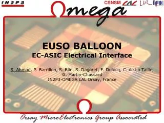
EC interface with PDM. PDM unit description. - The PhotoMultiplier (MAPMT) and the Filters - The ASIC (ASIC) - The Elementary Cell (EC) - The High Voltage Power Supply (HVPS) and Switches (SW) The PDM Board (PDMB). Size and Power estimation need to be complete.

E N D
PDM unit description - The PhotoMultiplier (MAPMT) and the Filters -The ASIC (ASIC) - The Elementary Cell (EC) - The High Voltage Power Supply (HVPS) and Switches (SW) • The PDM Board (PDMB)
Electrical mechanical Interfaces PDM board (Pierre or Salleh) HV boxes (Philippe Gorodetzky) Mechanical Interfaces PDM structure layout (Pierre) PDM board (Pierre or Salleh) HV Box Design (Philippe Gorodetzky)
Defineelectrical interfaces betweenSubsystems Power use (voltage, current …) Mass and size Grounding plan Connectors type and gender, locking Sub-system pinout Wires type (flex, HT, standard,…) CAO Model version updated. Plan to power on Ground
Data Processor:Block diagram DP LVPS 28V V, A Monitor v 12V 28V HK system SIREN system HL-CMD CPU RS232 v V, T monitor RS232 5V 5V CCB v SpaceWire to GbE/ PCI SpaceWire 12V, 5V, 3.3V v Analog (V, T) Data Storage v SATA CLKs,Sync, Trig Gbit-Ether. or PCI v 5V CLK board v SpaceWire I2C or SPI Visible cam (adv. opt.) Fast parallel link v USB v RS232 3.3V GPS v USB? PDM box IR Camera (adv. opt.) PWP SpaceWire?
PDM unit description - The PhotoMultiplier (MAPMT) and the Filters -The ASIC (ASIC) - The Elementary Cell (EC) - The High Voltage Power Supply (HVPS) and Switches (SW) • The PDM Board (PDMB) • Define external interfaces
Gondola CNES equipments • SIREN (TM/TC) 290 x 285 x 84 mm, 3.175 kg 12-18V, 13 W 24 H autonomy with 3.9 kg batteries • ICDV (Attitude measurement, shock, T°…) 210 x 175 x 88 mm, 1 kg 12-28V, 10 W Inertial measurement unit : 3 gyrometers +/- 300°/s 3 accelerometers +/- 18g magnetometer 3 axis, Attitude restitution : ~1°, 100Hz Accelerometer 3 axis +/- 50g, 0-800Hz 1 PT100 thermal sensor -60 +100°C 23 H autonomy with 1.2 kg batteries
Interfaces • Connectors type and gender, locking • Connectors tests for AIT • Protocol to Nosyca? • Protocol to Siren? • DefineNosyca, Siren, DP interfaces • Provide Tests Connectors for AIT • IRcamera, mechanical & electrical interfaces • Pixels numbering on the EC Unit • Define and RoutingHarness • FixHarness • External Power connectors. • Power budget on eachsub system • Pack batterydefinition
Environment • Thermal studies to 10°C guaranted ? • Heating or cooling ? • Groundingscheme • Power supply (Pack Batteries 250W/34.5Ah, 28V) enough? • Heating on L1? Thermal studies? • If heating power needed • On the Spider? Electricalheating or routing DP heating? • Wifi Antenna power? Direction? EMC? Wiredaccess possible withNoscycainstead of Wifi? • Shieldingscheme (wifi perturbation?) • Test withNosyca simulator? EGSE? • Transport vibration? • ESD discharge due to Lens