Download
1 / 29
330 likes | 643 Views
INSTALLATION INTERFACING CONTROLLING. INSTALLATION Mounting. INTERFACING Peripheral Equipment Data Collection Computer. SONIC 2024/2022 SONAR INTERFACE MODULE (SIM) Box. X. X. X. X. X. X. X. X. X. X. GPS 1 PPS Pulse (BNC Only). R2Sonic Data Packet Output.

E N D
INSTALLATION • INTERFACING • CONTROLLING
INSTALLATION Mounting
INTERFACING Peripheral Equipment Data Collection Computer
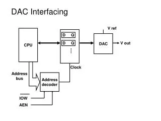
SONIC 2024/2022 SONAR INTERFACE MODULE (SIM) Box
X X X X X X X X X X
GPS 1 PPS Pulse (BNC Only) R2Sonic Data Packet Output GreenLights = Good Data RedLights = Incorrect Data or Setup X X X X X GPS NMEA Time $GPZDA Realtime Sound Velocity Probe (Format: <sp> xxxx.xxx m/sec) MRU Roll Stabilization TSS1 data string
From your computer’s Control Panel, • Open the Network Connections • Select your LAN Connection • Highlight the “Internet Protocol (TCP/IP)” • Click on the “Properties” button • Enter the IP Address and Subnet Mask below
Settings • Network Settings • Connect ALL R2Sonic Cables and “Power ON” the R2Sonic SIM Box • Click on the “Discover” button • If the Network IP Address is set correctly on your computer, the Sonic Controller will automatically find the R2Sonic Sonar and establish communication with it
Settings • Sensor Settings • Enable and Configure : • GPS Input settings • Motion (MRU/IMU) Input • Settings for Roll Stabilization • SVP (Sound Velocity Probe) • Input Settings • Match the ‘jumper’ setting • inside your 1PPS Box to • to the correct Edge (Rising • or Falling)
1 PPS Box Jumper Settings This Special Setup allows for the PPS Pulse to come in on Pin 9 from the GPS Serial connection and then Output thru the BNC connection Rising Edge Falling Edge
Settings • Ocean Settings • In waters with a large sediment load, the suspended particles will scatter the sound wave, thus leading • to transmission loss. In the scattering process, there is also a degree of energy that it is reflected • (backscatter); this can be a cause for ‘noise’ in the sonar data. Again, the surveyor should be aware of • this condition and, if need be, change the operating parameters of the Sonic 2024/2022. • It is generally a matter of increasing transmit power or pulse length to get more total power into the • water. In some circumstances, increasing the Absorption value will allow the system to rapidly increase • gain to capture the reflected energy that has been dissipated by seafloor absorption or scattering in the • water column. • As noted above many of the effects of absorption, scattering, and bottom absorption are frequency • dependent. With the Sonic 2024/2022, the operator can adjust the sonar frequency to optimise the • system for the survey conditions. This will take some trial and error; however, lower frequencies • tend to do best in areas of absorbent bottom and high sediment load (scatter).
Settings • Display Settings Set Colors to User Preference
Settings • Sonar Settings • From this Window, you • will be able to Control the • majority of settings that • will influence the data that • you will receive from the • R2Sonic Sonar
Frequency • With the Sonic 2024/2022, the operator can adjust the sonar frequency to optimise the system for the survey conditions. • This will take some trial and error; however, Lower frequencies tend to do best in areas of absorbent bottom and high sediment load in the water column (scatter).
Bottom Sampling EquiAngular EquiDistant
Roll Stabilization Without Roll Stabilization With Roll Stablization
Controller -- Main Display To change a Control Setting value, position the mouse cursor over the button Use the LEFT mouse button to Decreasethe value And the RIGHTmouse button to Increasethe value. System Information: • W: Wedge sector (opening angle) • T: Sector Tilt angle • G: Minimum and maximum depth gates • f: Operating frequency • c: Sound velocity at the sonar head • PR: Ping rate • D: Nadir depth
Control Value Ranges Range: 0 – 500 m Power: 0 – 221 dB Pulse Length: 15 – 500μsec Gain: 1 – 45 Depth Gate Min should be set just above the most Minimum depth in the swath Depth Gate Max should be set just below the most Maximum depth in the swath