Download
1 / 23
230 likes | 306 Views
Assignment. 1) Explain how lower address bus is multiplexed with data bus? 2) Explain the function of all the control signals in the 8085 Control Logic Subsystem. 3) What is the use of stack pointer? Give two examples and explain both of them.

E N D
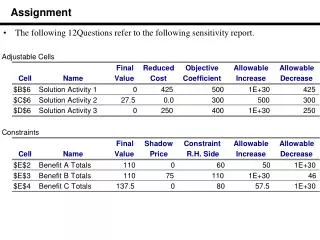
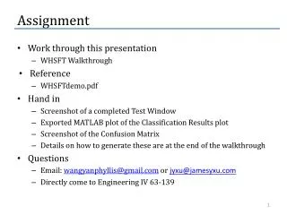
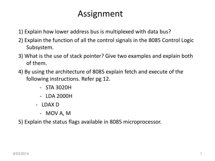
Assignment 1) Explain how lower address bus is multiplexed with data bus? 2) Explain the function of all the control signals in the 8085 Control Logic Subsystem. 3) What is the use of stack pointer? Give two examples and explain both of them. 4) By using the architecture of 8085 explain fetch and execute of the following instructions. Refer pg 12. - STA 3020H - LDA 2000H - LDAX D - MOV A, M 5) Explain the status flags available in 8085 microprocessor.
1) Translate the program into machine codes manually. 2) Show the values of program counters and the content of stack pointers during the execution process of PUSH PSW & RET 3) How much time is required to execute the program by using 3MHz crystal. org 1000h lxi sp,3000h mvi a,10 lxi h,data1 add m cc mmm sta result jmp exit mmm: push psw sui 20h sta 2020h pop psw ret exit: end org 2000H data1: dfb FFh,22h,33h result: dfs 1
What is an Interrupt ? • A hardware interrupt is a CPU facility which permits spurious asynchronous events to suspend program execution and instead execute a software module to service the event. • The connection to the processor which allows external devices to signal a request for service is called an interrupt pin. • The software module that the processor executes in response to an interrupt is called an interrupt service routine ( ISR ). • The interrupt mechanism is such that after completion of the ISR the processor returns to execution of the main program from the point at which it was interrupted.
Direct and Vectored Interrupts • With direct interrupts, the interrupting device need to provide the interrupt signal only. i.e. to assert the signal to the interrupt pin of the processor. • With direct interrupts the address of the first instruction of the ISR for the particular interrupt is pre-programmed into the CPU. • With vectored interrupts the interrupting device has to supply both the interrupt signal and the 16-bit address of the first instruction of the ISR. • Interrupt service routines for vectored interrupts can reside anywhere in the memory map of the computer system.
Maskable and Non-maskable Interrupts • A non-maskable interrupt will always, if asserted, interrupt the processor. There is no software mechanism to prevent the processor being interrupted by a non-maskable interrupt. • A maskable interrupt, if asserted, will only interrupt the processor if it is enabled ( unmasked ). Maskable interrupts can be enabled ( unmasked ) or disabled ( masked ) by software. • Most maskable interrupts automatically become disabled (masked) after an interrupt has occurred. It requires further software commands to re-enable maskable interrupts.
Interrupt Priority • For processor with multiple interrupt input pins, the various interrupts are assigned a priority. • When simultaneous interrupts occur the highest priority interrupt will be serviced before lower priority interrupts. • It is possible to arrange software such that whilst a lower priority interrupt is being serviced that a higher priority interrupt can interrupt the lower priority service routine.
InterruptTrigger Type Trap Rising Edge AND High Level RST 7.5 Rising Edge RST 6.5 High Level RST 5.5 High Level INTR High Level
Enabling and Disabling Maskable Interrupts • The DI (disable interrupts) instruction disables all maskable interrupts. • The EI (enable interrupts) instruction enables the vectored interrupt INTR and the unmasked restart interrupts RST 5.5, RST 6.5 and RST 7.5. • The interrupt mask for the restart interrupts is determined by the contents of the accumulator when the SIMinstruction is executed.
EXAMPLE (Enable/Disable Direct Interrupt) For example to disable RST 7.5 and RST 5.5 and enable RST6.5 MVI A, 00011010B SIM ;Set Interrupt Mask EI ;Enable Interrupt
ORG 0000H JMP START ORG 0034H JMP ISR65 ORG 003CH JMP ISR75 START: …. MVI A, 00011010B SIM EI ….. ….. ISR65: ….. ….. RET ISR75: ….. ….. RET
Machine Cycles with Direct Interrupts • Since there is no requirement to supply ISR addresses with direct interrupts ( TRAP, RST 5.5, RST 6.5 & RST 7.5 ) then there is no requirement for the 8085A to execute INA machine cycles in response to such interrupts. • However to provide the CPU sufficient time to process a direct interrupt a six T-state bus idle machine cycle is introduced, following recognition of the direct interrupt. • During the bus idle machine cycle no control signal is asserted nor is the program counter incremented. Ready line control is ignored during the bus idle cycle. • Following the bus idle cycle two memory write cycles are executed to save the current contents of the program counter on the stack. • The program counter is then overwritten with the pre-programmed address for the particular interrupt source.
Machine Cycles with Vectored Interrupts • The 8085A processor executes a number of machine cycles, in response to a vectored interrupt (intr), prior to execution of the first instruction of the interrupt service routine. • The processor completes the execution of the current instruction. (Note : The processor only samples the interrupt inputs in the last T-state of the last machine cycle in the current instruction cycle) • This has implication in system design as it means that the interrupt signal on INTR must remain in the asserted state for at least the longest instruction in the 8085A instruction set to guarantee that the processor recognises the interrupt.
Machine Cycles with Vectored Interrupts • The processor then executes a six T-state interrupt acknowledge machine cycle ( the INTA machine cycle is similar to the opcode fetch machine cycle except that the program counter is not incremented and the INTA* control signal is asserted instead of RD*) • In response to the INTA* signal, the interrupting device need to place the opcode of an instruction onto the data bus ( called jamming ). • The processor reads the opcode in the normal manner and stores it in the instruction register. • The choice of opcode is restricted as it is necessary to automatically save the contents of the program counter to enable the program to return to the point in the software where it was interrupted.
Machine Cycles with Vectored Interrupts (CALL) • The only viable choice of 8085A instruction is either the CALLinstruction or the RST n instruction. • The CALL instruction is a 3-byte instruction with bytes 2 & 3 being the address of the first instruction of the subroutine ( in this case the interrupt service routine). • Following decoding of the call opcode, the processor executes a further two interrupt acknowledge machine cycles to fetch the address of the start of the ISR. • It is incumbent on the interrupting device to place thelow byte of the address of the ISR onto the data bus in response to the second INTA* control signal and the high byte of the address in response to the third INTA* signal.
Machine Cycles with Vectored Interrupts (CALL) • The execution phase of the CALL instruction can now take place. • The processor firstly executes two memory write machine cycles to save the current contents of the program counter onto the stack. The address as to where in memory the contents of PC is to be saved is specified by the stack pointer register. • Finally the processor overwrites the contents of the program counter with the second and third bytes of the call instruction. • The next instruction the processor will execute will be the first instruction of the ISR.
Vector Interrupts (RST n) • The Restart instruction, RST n, where 0 ≤ n ≤ 7 RST n ((SP)-1) (PCH) ((SP)-2) (PCL) ((SP) (SP) – 2 (PC) 8 * n
Vector Interrupts (RST n) • In respond to the INTA strobe, external logic places an RST n opcode on the data bus. • RST n has the following bit pattern 11NNN111 where n=NNN (3 bit binary number) and restart address is n * 8 For example if RST 1, NNN = 001 and restart address is 8 (RST 2 (address 10H), RST 3 (address 18H) etc)