Download
1 / 25
250 likes | 597 Views
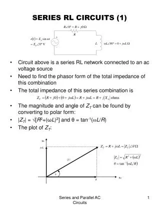
Inductance and RL Circuits. Mutual Inductance Self Inductance RL Circuits Magnetic Energy. Inductance. Mutual Inductance On the table you will find two coils. The larger coil is connected to a AC power supply. This will apply a sinusoidal voltage given by V(t) = V 0 sin( w t).

E N D
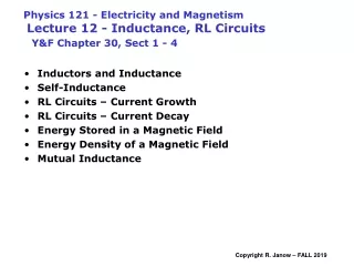
Inductance and RL Circuits Mutual Inductance Self Inductance RL Circuits Magnetic Energy
Inductance • Mutual Inductance On the table you will find two coils. The larger coil is connected to a AC power supply. This will apply a sinusoidal voltage given by V(t) = V0sin(wt). This voltage produces a sinusoidal current in the large coil where I(t) = I0sin(wt) The angular frequency w is 2p times the frequency. This will give us a time varying magnetic field in the large coil. • Describe the change in the magnetic field as a function of time (do not use sine).
Inductance • Mutual Inductance V(t) = V0sin(wt). I(t) = I0sin(wt)
Inductance • The smaller coil is connected to the voltage input on the Pasco 750 Interface. Start Data Studio and configure the interface for Voltage input by selecting and dragging the analog icon (the plug icon on the left side) to channel A. For output select Scope (the oscilloscope) and connect to channel A by dragging the icon to channel A. Enlarge the window. On the right side of the oscilloscope display window you will find two controls. The left control should control the sensitivity of the input (vertical scale). Set the voltage for channel A to 0.1 volts/div by clicking the vertical trace scale button. At the bottom of the window you will find the button to change the sweep rate. Change the time sweep to 10 msec/div.
Inductance • Turn on the AC supply and turn the knob to full scale (12 volts). Place the smaller coil inside the larger coil with the axis of the small coil aliened with the axis of the large coil. You should see a sine wave trace on the oscilloscope screen. If you do not get help from the instructor. • Slowly pull the small coil out of the large coil along the coil axis. Describe what happens to the voltage signal in the small coil. • Return the coil to the center of the large coil. Rotate the small coil on its side by 90 degrees then 180 degrees. Describe what happens to the voltage signal.
Inductance • Write the equation that describes the emf induced in one coil when there is a current changing with time in the other coil. • This equation describes the results that you just observed. large coil small coil
Inductance • Repeat the experiment again where you slowly pull the small coil out of the large coil. Explain what happen using the equation and the definition of mutual inductance. • Did the mutual induction change? Explain.
where f is the flux through one coil and I is the current in the other. small coil Inductance • Let’s calculate the mutual inductance for the two coils when the small coil is in the center of the large coil. What is the definition of mutual inductance? Which coil should we use to calculate the magnetic field? The larger coil because the flux through the smaller coil can be calculated assuming the magnetic field is constant.
Inductance • Calculate the magnetic field due to the largest coil. • Calculate the flux through the smaller coil. • Calculate the mutual inductance.
Inductance Self Inductance • Self inductance is just like mutual inductance except that there is one coil instead of two. The self inductance comes from the current in the coil producing a flux through the coil and thus a emf in the coil. Because of the minus sign the induced emf is in the opposite direction from the applied emf that caused the initial current. It is thus called a “back emf”. In Example 32-3 the authors find the self inductance for a solenoid. Look up the equation for the self inductance for a solenoid and enter it here. • Why are there no subscripts on f and I?
Inductance • Calculate the self inductance for the small coil you have been using. The coil has 400 turns and a radius of 1 cm.
battery 110 VAC Inductance Applications: Toothbrush Inductance Charger
Input Output Inductance Applications: Transformer High voltage transformer Low voltage transformer
Inductance Applications: Inductors We will see their use in the next lecture.
Inductance LR Circuits • On your table you will find the E&M board with resistors capacitors, and an inductor. Connect the inductor and the 470 W resistor in series with the Sweep/Function Generator. Use the cable with four leads. The two leads with the black and white plug are the voltage input leads and the two leads with the red and blue plugs are the output from the signal generator. The red cable with the white plug is the positive side or higher potential side. The Sweep/Function Generator produces different types of voltages. Select the square wave by pressing the square wave button on the upper right side. Set the amplitude to 2 volts and a frequency of 20 Hz. Connect the voltage input to the Pasco interface to the output of the Sweep/Function Generator.
Inductance • You should still have Science Workshop open with the voltage input and the oscilloscope as an output for channel A. Set the vertical scale for 2 volts/div and the horizontal scale to 5 ms/div. You should see a square wave of the screen. Change the amplitude on the Sweep/Function Generator and watch the signal change. Does it change the way you expect? • Now change the frequency on the Sweep/Function Generator. Watch the square wave trace change. Does the trace change the way you expect? Can you relate the period measured on the screen to the frequency of the Function Generator? Do it. Measure the period and calculate the frequency. • Does it compare with the frequency on the Function Generator?
Inductance • Change the frequency back to 20 Hz. and connect the voltage probes to the 470 W resistor. The voltage across the resistor is proportional to the current. The voltage across the resistor and the current have the same functional form. You should see the trace rise and level off. This is what your text calls current build up in an inductor. This is described by the following equation • where the inductance time constant t =L/R. Discuss in your group. What will happen if you increased the resistance. Write your answer here. • Change the resistor in the circuit two or three times and see if you were correct.
Inductance • Now close the oscilloscope window and connect the graph window to channel A the voltage input. Set the time scale to msec and the voltage scale to +2 volts and -2 volts. Make sure the resistor is the 470 W resistor and record the voltage across the resistor for one or two seconds. Click the box that rescales the graph to the data and then click the box that allows you to select and rescale. Get one full period on the screen. You can see current build-up and decay. • Discuss in your group the value of the voltage for one and two time constants. Use this to find the time constant. • Do you get the same time constant for current build-up and decay? Check this out.
Inductance • From the time constant and the resistance find the self inductance for the inductor. An ideal inductor has zero resistance, but a real inductor has a resistance. It is the resistance of the wire that forms the inductor. This resistance is part of the time constant. The total resistance is the 470 W resistor and the 165 W resistance of the inductor
B A Inductance RL Circuit – Current Build-up and Decay
Inductance RL Circuit – Current Decay + -
Inductance RL Circuit – Current Build-up
Inductance RL Circuit – Current Build- up +
Inductance RL Circuit – Resistor and Inductor in Parallel On current build-up VL ~ dI/dt t ~ t Slope dI/dt t ~ 3-4 t So most of the current goes through the resistor.
Inductance Energy in an Inductor • Look up the energy stored in an inductor and write it here. • Is the energy constant in the circuit you are using? Explain. • If the maximum current in the inductor is 40 mAmps, what is the maximum energy stored in the inductor? • What is the energy in terms of the magnetic field? U = (1/2)(25mH)(40mA)2 =