Download
1 / 36
460 likes | 778 Views
KLINGE’S NMR 262 Two Independent Systems Integrated into one Unit. This Requires Special Features: Total Redundancy of Refrigeration Components Total Redundancy of Electric Controls Communication between the two Independent Systems. Basic Refrigeration System. Air Flow.

E N D
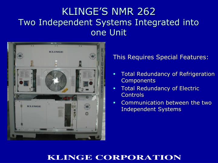
KLINGE’S NMR 262Two Independent Systems Integrated into one Unit This Requires Special Features: • Total Redundancy of Refrigeration Components • Total Redundancy of Electric Controls • Communication between the two Independent Systems
Each System has its own Control Box Located on the Left side of the Unit is the Control Box designated as 1 Located on the Right side of the Unit is the Control Box designated as 2 Each Box Controls the Compressor Directly behind it and its associated refrigeration system Each Box Controls the Evaporator Fan on its side of the Evaporator Section The Boxes Communication with each other to Control the entire Unit
Probes Provide Temperature Feedback to the Controllers Top Photo shows Return Air Probes (left and right) from Container side of the Unit and Recorder Return Air Probe (middle) Bottom Photo shows Right side of Evaporator Coil looking into the Evaporator Section • Notice Return Air Probe (upper one) pushed through the coil • The Defrost Probe (lower one) is positioned between the lines of the coil to sense the temperature of the Evaporator coil Each Independent System has its own Probes • One Return Air Probe • One Defrost Probe
As previously stated the Unit has two Independent Control Boxes with a Communications Link joining them Both Control Boxes MUST be turned on for Proper Unit Operation Each Control Box has its own ON-OFF switch The Box that is turned On FIRST will become the Primary Control for the Unit The Box that is turned On SECOND will become the Secondary Control Note that there is no difference between starting Control Box 1 or 2 first, either one is capable of operation as the Primary Control Then by default the other Box will operate as the Secondary Control, but remember it MUST also be turned on Starting the UnitPrimary Control versus SecondaryControl
Proper LED Configuration for Thermostats of Primary Control Box • The Green ON LED should be activated • The Yellow PRI SYSTEM LED should be activated • The Yellow COOLING LED should be activated
Proper LED Configuration for Thermostats of Secondary Control Box • Only the Green ON LED should be activated if the Control Box is functioning as the Secondary Control
Alarm Conditions • Each Control Box has its own Electronic Thermostat • The Thermostats have Fault LEDs to be activated if a system fault is detected • If a problem develops with the Primary System the Communication link between the two independent systems will execute a System Change. • The Secondary Control System will take over as the Primary Control System • The Primary Control System will become the Secondary Control System • This System Change is an automatic function of the NMR 262 • If the Thermostat of the Primary Control System detects a significant problem and executes a System Change it will activate the Alarm Horn and the corresponding Alarm Light of the Evaporator section.
Operator Interface Each Control Box has 3 external switches and an internal Touch Pad Display The top switch is the ON-OFF switch referred to earlier The 2nd switch is for Manual Defrost and to silence the Alarm Horn The 3rd switch is to Reset the control circuit breaker (CB2) The Touch Pad Display is used to enter the Desired Set Point and display the Return Air Probe temperature • Note that only the Primary Control System will have its Display activated • The Secondary System’s Display can be momentarily activated by pressing any of the 3 touch pad switches
Older model NMR-262 with thumb wheel set point 7 mechanical recorder
The engine of this genset is equipped with an automatic glow plug system, set to operate when engine black temp is below 13° Start engine by momentarily placing “MAN / OFF / AUTO” switch in the “MAN” or “AUTO” position. If the switch is in the “MAN” position and engine fails to start, reset the controls by momentarily placing the switch in the “OFF” position. If the switch is in the “AUTO” position, engine control unit “ECU” is set from factory for 8 starting cycles. If engine did not start at the end of 8 cycles, reset controls by placing the switch in “OFF” position and check engine. Automatic shut-down indicators are located inside electric box for low oil pressure, high oil temp, and starter overcrank. If switch is in “MAN” or “AUTO””, but engine is not running, one of the shut-downs has activated. Reset by momentarily placing the switch “OFF”.
KLINGE MAINTENANCE PARTS OIL FILTER K26 24898 14 FUEL FILTER PRIMARYK22 06905 00 FUEL FILTER SECONDARYK26 24898 13 AIR FILTER CARTRIDGEK26 25091 08 V-BELT ALTERNATORK26 24898 10USE SAE 10W 40 OIL – API RATING CF/CF-4
This Unit Is Equipped with an Engine Control Unit (ECU) KLINGE P / N K31 00826 00 • THE ECU AUTOMATICALLY CRANKS, STARTS & MONITORS ENGINE FOR OVERCRANK, OVERSPEED, HIGH COOLANT TEMP, & LOW OIL PRESSURE. • THE ECU IS LOCATED IN THE ELECTRICAL BOX AND USES SIGNALS FROM A MANGETIC PICKUP P/N K25 26241 02 TO MONITOR ENGINE DURING CRANKING & RUNNING. • THE MAGNETIC PICKUP IS LOCTED CLOSE TO THE BOTTOM OF THE ENGINE’S FLYWHEEL HOUSING & IS CONNECTED TO THE CONTROL BOX BY SHIELDED 2 CONDUCTOR CABLE. • IF THE SIGNAL FROM THE PICKUP IS NOT RECEIVED DURING CRANKING, ENGINE WILL NOT START. IF THE SIGNAL IS LOST WHEN UNIT IS RUNNING, ENGINE WILL SHUT OFF. IN BOTH CASES THE OVERCRANK & OVERSPEED LED’s OF ECU WILL ACTIVATE. (CONTINUED)
FOR PROPER OPERATION THE GAP BETWEEN THE TOP OF THE MAGNETIC PICKUP & THE TOP OF THE ENGINE’s FLYWHEEL SHOULD BE 0.53 mm. THIS GAP IS OBTAINED BY INSERTING THE PICKUP UNTIL IT LIGHTLY TOUCHES A FLYWHEEL TOOTH & THEN BACKING IT OUT BY ½ A TURN. TO MAKE SURE THIS GAP IS MAINTAINED, CHECK FROM TIME TO TIME THAT THE LOCKNUT ON THE MAGNETIC PICKUP IS TIGHT. • IF THE SIGNAL FROM THE PICKUP IS NOT RECEIVED DURING CRANKING, ENGINE WILL NOT START. IF THE SIGNAL IS LOST WHEN UNIT IS RUNNING, ENGINE WILL SHUT OFF. IN BOTH CASES THE OVERCRANK & OVERSPEED LED’s OF ECU WILL ACTIVATE. • IT THE MAGNETIC PICKUP MUST BE REPLACED MAKE SURE THAT DURING INSTALLATION IT FACES THE HIGHPOINT OF A FLYWHEEL TOOTH, TO ENSURE THIS USE A FLASH LIGHT TO LOOK THROUGH THE MOUNTING HOLE & SLIGHTLY TURN ENGINE UNTIL HIGHPOINT OF A TOOTH FACES THE HOLE. • THERE ARE 4 POTS TO ADJUST THE CONTROL SETTINGS & 5 SWITCHES TO SET THE CRANK CYCLES AS SHOWN IN THE SKETCH. • TURNING THE POTS CLOCKWISE INCREASES THE SETTINGS, POTS ARE 25 TURNS AND CAN NOT BE DAMAGED BY EXCESS TURNS. • SWI, SW2 & SW3 SHOULD BE ON, SW4 & SW5 SHOULD BE OFF.
Located Inside the Genset Door is a Maintenance Schedule for the Deutz Engine
THE ENGINE OF THIS GENSET IS EQUIPPED WITH AN AUTOMATIC GLOW PLUG SYSTEM, SET TO OPERATE WHEN ENGINE BLOCK TEMP IS BELOW 13˚C. START ENGINE BY MOMENTARILY PLACING “MAN / OFF / AUTO” SWITCH IN THE “MAN OR “AUTO” POSITION. IF THE SWITCH IS IN “MAN” POSITION AND ENGINE FAILS TO START, RESET THE CONTROLS BY MOMENTARILY PLACING THE SWITCH IN THE “OFF” POSITION. IF THE SWITCH IS IN “AUTO” POSITION, ENGINE CONTROL UNIT “ECU” IS SET FROM FACTORY FOR 8 STARTING CYCLES. IF ENGINE DID NOT START AT THE END OF 8 CYCLES, RESET CONTROLS BY PLACING THE SWITCH IN “OFF” POSITION AND CHECK ENGINE. AUTOMATIC SHUT-DOWN INDICATORS ARE LOCTED INSIDE ELECTRIC BOX FOR LOW OIL PRESSURE, HIGH OIL TEMP AND STARTER OVERCRANK. IF SWITCH IS IN “MAN” OR “AUTO”, BUT ENGINE IS NOT RUNNING, ONE OF THE SHUT-DOWNS HAS ACTIVATED. RESET BY MOMENTARILY PLACING THE SWITCH “OFF”.
Pre-Trip Form for NMG-115 Change lube oil filters every 500 hours