Download
1 / 38
390 likes | 506 Views
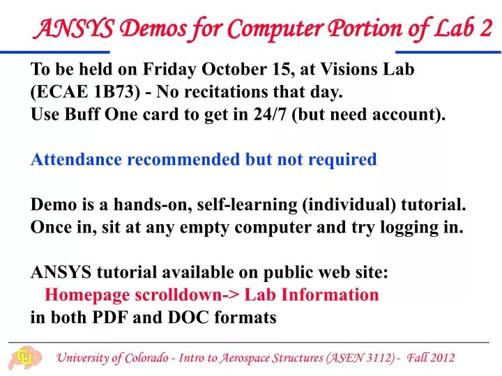
ANSYS Demos for Computer Portion of Lab 2. To be held on Friday October 15, at Visions Lab (ECAE 1B73) - No recitations that day. Use Buff One card to get in 24/7 (but need account). Attendance recommended but not required Demo is a hands-on, self-learning (individual) tutorial.

E N D
ANSYS Demos for Computer Portion of Lab 2 To be held on Friday October 15, at Visions Lab (ECAE 1B73) - No recitations that day. Use Buff One card to get in 24/7 (but need account). Attendance recommended but not required Demo is a hands-on, self-learning (individual) tutorial. Once in, sit at any empty computer and try logging in. ANSYS tutorial available on public web site: Homepage scrolldown-> Lab Information in both PDF and DOC formats
Demo Times Because of limited seating (physically 25 workstations but only 23 are operational) the demo will be divided into four roughly-one-hour subsections Sec 011: 10 and 11PM Sec 012: 1 and 2PM Student distribution on next slide
Section 013 (10-11:50AM) Splitting A-N 10 AM O-Z 11 AM
Section 012 (1-2:50 M) Splitting A-L 1 PM M-Z 2 PM
No Grouping Necessary Note: members of a group need not attend the same demo subsection, since the tutorial is individual
Before 1950, standard structural elements such as beams, ribs and spars, were sufficient for modeling low aspect ratio aircraft structures (e.g. Lockheed Constellation, pictured on left)
The modern FEM was developed ... ... starting about 1952 as a modeling tool to simulate delta wing military aircraft on digitalcomputers Digital computers began to be commercially sold by 1951. Only aerospace companies and some government agencies could afford them (a vacuum-tube monster weighting several tons cost the equivalent of $100M today)
The method was well on its way by 1960 ... but it had a marketing problem: no brand name
Ray Clough’s early career I b. 1921, Washington state served in Air Force during WWII Ph.D. Aero & Astro MIT, 1950 joined Civil Engrg faculty at UC Berkeley, 1951 avid mountaineer & skier (holds many climbing records)
Ray Clough’s early career II spent 1952-54 summers at Boeing at Jon Turner’s group so he could go mountain climbing on weekends modern FEM started by 1956 JAS paper by Turner, Clough, Martin & Topp back at Berkeley, became interesting in Civil applications, especially earthquake engineering formed active FEM research group in 1958
Ray with Kurt Gerstle (his 1st student) on left pic 2002 1956
Ray Clough’s late career gave up FEM research in 1972 for seismic engineering head of NSF Earthquake Engineering Center at Richmond, CA, 1974-82 retired from Berkeley 1987 honored with National Medal of Science, 1994
Explosive Success ... By 1970, FEM (DSM) had taken over computational mechanics and was expanding beyond structures Some samples follow
F-16 Exterior Surface Zoom 95% of elements are HPSHEL3 18 DOF shells
F-16 Interior Structure Zoom Some solid elements (bricks & tets) used for “wing fingers”
The Troll Platform • 470 m high including superstructure • 240 000 m3 of concrete • 104 000 tons of steel reinforcement • Design life of 50 years • Largest man-made object ever moved • Supplies 10 percent of Europe’s gas consumption
The Heidrun Platform • Floating TLP Platform • Made of reinforced concrete • 16 vertical anchoring lines (tethers) • 30 000 of pre-tensioning • Transverse stiffness supplied by secondary geometric effects