Download
1 / 16
160 likes | 281 Views
D. I. The previous protection methods. 2. The improved protection method (J. R. Lucas Method). O : Point of lightning stroke S 0 : Rate of rise at O, kV/µs I 0 : Lightning stroke current , kA X :Distance in which a surge with an infinite

E N D
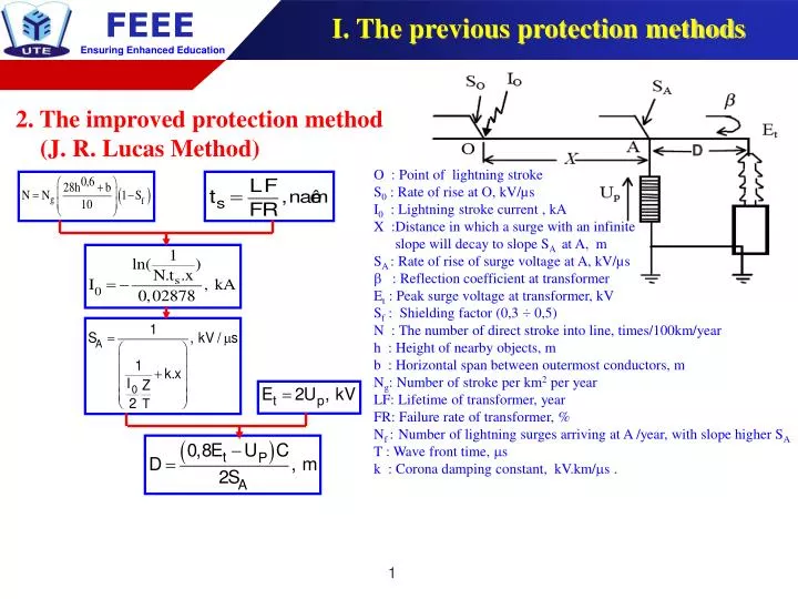
D I. The previous protection methods 2. The improved protection method (J. R. Lucas Method) O : Point of lightning stroke S0 : Rate of rise at O, kV/µs I0 : Lightning stroke current , kA X :Distance in which a surge with an infinite slope will decay to slope SA at A, m SA : Rate of rise of surge voltage at A, kV/µs : Reflection coefficient at transformer Et : Peak surge voltage at transformer, kV Sf : Shielding factor (0,3 ÷ 0,5) N : The number of direct stroke into line, times/100km/year h : Height of nearby objects, m b : Horizontal span between outermost conductors, m Ng: Number of stroke per km2 per year LF: Lifetime of transformer, year FR: Failure rate of transformer, % Nf :Number of lightning surges arriving at A /year, with slope higher SA T : Wave front time, s k : Corona damping constant, kV.km/s .
D I. The previous protection methods 2. The improved protection method (J. R. Lucas Method) O : Point of lightning stroke S0 : Rate of rise at O, kV/µs I0 : Lightning stroke current , kA X :Distance in which a surge with an infinite slope will decay to slope SA at A, m SA : Rate of rise of surge voltage at A, kV/µs : Reflection coefficient at transformer Et : Peak surge voltage at transformer, kV Sf : Shielding factor (0,3 ÷ 0,5) N : The number of direct stroke into line, times/100km/year h : Height of nearby objects, m b : Horizontal span between outermost conductors, m Ng: Number of stroke per km2 per year LF: Lifetime of transformer, year FR: Failure rate of transformer, % Nf :Number of lightning surges arriving at A /year, with slope higher SA T : Wave front time, s k : Corona damping constant, kV.km/s .
I. The previous protection methods • The previous methods: • Accounting for influence elements with some experiment parameters • Just considered to single transformer substation • The proposed method: • Determining surge arrester‘s location for 3-line, 2-transfomer substation based on: • IEEE Std C62.22.2009 • Influence elements (can be calculated) • Mean Time Between Failure (MTBF) of Transformer
II. The proposed protection method The proposed protection method based on IEEE Std C62.22.2009 (3-line , 2 - transformer substation) S.1.Eliminate 1 transformer and determine the line which the lightning wave transmitted into. S.2.Define the following parameters: - J, the common point between transformer, surge arrester and the line identified in step 01. - D1, distance from J to pole-mounted transformer - D2, distance from arrester to ground d2 = A, B, C: Line A, B, C. T1,T2 : Transformer T1 and T2 D1: Separate distance between T1 and line, m. D2: Separate distance between T2 and line, m. Ntt: Number of identified lines S.3.Eliminate all line connected to D1 S.4.Calculate SJ , kA/s
II. The proposed protection method The proposed method based on IEEE Std C62.22.2009 S.5.Distance : stroke - substation , km with: B: insulation equipments. d1: distance between line and arrester , m. D2: distance between arrester and ground, m. S : slope wave, kA/s. MTBF: mean time between failure, year FR: acceptable failure rate, % N : number of stroke into line, times /100 km/year Kc: corona damping constant , kV.km/s Va: Mức bảo vệ đầu sóng của chống sét van tại 0,5s, kV Z : line impedance, L : Inductance, H. S.6. Voltage of Arrester
II. The proposed protection method The proposed protection method based on IEEE Std C62.22.2009 S.7. Determine D1 and D2: D1 = min (D1_T1_Line A ; D1_T1_Line B ; D1_T1_Line C) D2 = min (D2_T2_Line A ; D2_T2_Line B ; D2_T2_Line C)
II. The proposed protection method Shielding Factor Object ‘s Height Nonlinear regression technique Curve Fitting Matlab (Sf) Build 16 relationships Sf, H và DO SfL: S.F at left side SfR: S.F at right side Sf = SfL + SfR Distance from objects to line (DO = x), m H = 10m: Sf = 5,013.10 - 7.x3 – 6,051.10-5.x2 – 0,003655.x + 0,4813 H = 14m: Sf = – 6,047.10 - 12.x5 + 1,452.10 - 8.x4 – 3,332.10 - 6.x3 +0,3459.10 - 3.x2 – 0,0247.x + 0,9982
II. The proposed protection method The number of stroke into line , times/100km/year The inductance line which connect to surge arrester - The inductance at line (length 1 m) , H/m Which: , m - The inductance line which connect to surge arrester , H
(3) (1) II. The proposed protection method Check MTBF of transformer Nonlinear regression technique Curve Fitting Matlab MTBF (year) Build 6 relationships Sf, H và DO Ng (times/km2.year)
III. OPSOLA Program 1. Introduction of OPSOLA Program OPSOLA (Optimal Placement Software Of Lightning Arrester ) Determine optimized arrester’s location Check MTBF of transformer Single phase, single transformer substation Three-phase, two-transformer substation
III. OPSOLA Program 2. Calculation Interface Main Interface Configuration
III. OPSOLA Program 3. Single line, single transformer Substation
III. OPSOLA Program 4. Three-line, two-transformer Substation
III. OPSOLA Program 5. Checking MTBF
IV. Result • Propose the improve method to locate the optimal position of surge arrester with different configuration of substations • Propose the method to determine the Mean Time Between Failure (MTBF) of substation with one transformer and to make sure that the life of transformeraccording to specified requirement • Construct 16 relationship characteristics between shielding object height, distance from the line to shielding object and shielding factor of distribution line and 6 relationship characteristics between MTBF, shielding factor and areas ground flash density • Build the OPSOLA program to help the users easily determine the reasonable distance and check MTBF of substation