Download
1 / 70
790 likes | 1.19k Views
MT 313 IC ENGINES. LECTURE NO: 02 (17 Feb, 2014) Khurram engr014@yahoo.com Yahoo Group Address: ICE14. HEAT ENGINES. I.C. Engines E.C. Engines Rotary Reciprocating Reciprocating Rotary Open Cycle Wankel Steam Stirling Gas Turbine Steam Close Cycle

E N D
MT 313 IC ENGINES LECTURE NO: 02 (17 Feb, 2014) Khurram engr014@yahoo.com Yahoo Group Address: ICE14
HEAT ENGINES I.C. Engines E.C. Engines Rotary Reciprocating Reciprocating Rotary Open Cycle Wankel Steam Stirling Gas Turbine Steam Close Cycle Gasoline Diesel Gas Turbine
Classification of I. C. Engines • Nature of Thermodynamic Cycle • 1. Otto cycle engine. • 2. Diesel cycle engine. • 3. Dual combustion cycle engine. • Type of the Fuel- used • 1. Petrol engine. • 2. Diesel engine. • 3. Gas engine. • 4. Bi-fuel Engine. • 5. Dual Fuel Engine
Classification of I. C. Engines • Number of Strokes • 1. 2 - stroke engine • 2. 4 - stroke engine • Method of Ignition • 1. Spark ignition engine, [S.I. Engine]. • 2. Compression ignition engine, [C.I. engine]. • Number of Cylinders • 1. Single cylinder engine. • 2. Multi-cylinder engine.
Classification of I. C. Engines • Position of the Cylinder • 1. Horizontal engine • 2. Vertical engine • 3. V- engine. • 4. Radial engine. • Method of Cooling • 1. Air cooled engine. • 2. Water cooled engine • Speed of the Engine • 1. Low speed engine. • 2. Medium speed engine. • 3. High speed engine.
Spark plug Valve Clearance volume TDC Bore Stroke BDC Piston I. C. Engine Terms and Definition • TDC (top dead center): It is the top most position of the piston towards head side of the cylinder • BDC (bottom dead center): The lowermost position of the piston towards the crank end side of the cylinder.
Stroke: • It is the linear distance traveled by the piston when it moves from one end of the cylinder to the other end • Bore: • It is the inside diameter of the cylinder. • Stock to Bore Ratio: L/d • d ˂ L Under Square • d =L Square • d ˃L Over Square
Swept volume or (Displacement volume) • It is the volume swept through by the piston in moving between TDC and BDC • Vs = A x L = (π/4)d2 L • Clearance volume: • It isthe volume contained in the cylinder above the top of the piston, when the piston is at TDC.
Total volume = swept volume + clearance volume. • Compression ratio: “r” • It is the ratio of total cylinder volume to clearance volume. r = Total volume = VT clearance volume VC Value of “r” for, petrol engine lies between 7 to 9 Diesel engine lies between 15 to 22 • Cubic Capacity VS x K ( K= No of Cylinders)
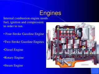
Working of 4-S Petrol Engine • The petrol engines work on the principle of “OTTO CYCLE”, also known as constant Volume cycle. • The engines operating on this cycle use either petrol or other spirit fuels or the gases such as LPG / CNG as their fuels.
In a 4-Stroke petrol engine, the chargeis admitted to the engine cylinder is a homogeneous mixture of petrol and air. • Depending on the load on the engine, the fuel and air is mixed in proper proportions and sent in to the cylinder by a popular device known as “carburetor”.
In a 4-stroke petrol engine there are four main events taking place, they are 1. Suction 2. Compression 3. Working or power or expansion, and 4. Exhaust So in a cycle there are four events to take place, and each of this is performed during a single stroke of the piston Since ignition in these engines is due to a spark, they are also called spark ignition engines .
INTAKE [Suction]: During the intake stroke, the piston moves down ward, drawing a fresh charge of vaporized fuel-air mixture, This operation is represented by the line AB on the P-V diagram. Pressure [P] TDC BDC A B Volume [V]
2. Compression Stroke: During compression stroke, the piston moves from BDC to TDC, thus compressing air petrol mixture. Due to compression, the pressure and temperature are increased and is shown by the line BC on the P- V diagram. Just before the end of this stroke the spark - plug initiates a spark which ignites the mixture and combustion takes place at constant volume as shown by the line CD D Pressure [P] TDC C BDC A B Volume [V]
3. Working Stroke: The expansion of gases due to the heat of combustion exerts a pressure on the piston. Under this impulse, the piston moves from TDC to BDC and thus the work is obtained in this stroke as shown by the line DE D Pressure [P] TDC C E BDC A B Volume [V]
4. Exhaust Stroke: At the end of the power stroke, the exhaust valve is opened & greater part of the burnt gases escapes because of their own expansion. The drop in pressure at constant volume is represented by the line EB. During this stroke the piston moves from BDC to TDC and pushes the remaining gases to the atmosphere. This stroke is represented the line BA on the P-V diagram. D Pressure [P] TDC C E BDC A B Volume [V]
D C Pressure E A B Volume Theoretical Otto cycle P V diagram for SI Engine / Otto cycle engine TDC BDC
Diesel Engines • This engine was invented in 1892 by a German mechanical engineer named Rudolph Diesel. • At first this engine was known as the compression engine but later was named Diesel after its inventor.
Diesel Engines • Diesels come in two stroke and four stroke versions and operate much like the gasoline driven engines. • Diesels have a greater compression ratio than gasoline engines. • Diesel 16:1 – 23:1 • Gasoline 6:1 – 12:1
Diesel Engine Principles of Operation • Intake Stroke • The intake valve opens. • The piston moves downward. • Only air is pulled into the cylinder or pumped in using a turbo charger (fan).
Diesel Engine Principles of Operation • Compression Stroke • The upward movement of the piston compresses the air increasing the temperature to approximately 538 degrees Celsius.
Diesel Engine Principles of Operation • Power Stroke • As the piston reaches the top, fuel is injected at just the right moment and ignited by the heat, forcing the piston back down.
Diesel Engine Principles of Operation • Exhaust stroke • The piston moves back to the top and pushes the burned gases out of the exhaust valve or port.
Working of 4-S Diesel Engine The basic construction of a four stroke diesel engine is same as that of four stroke petrol engine. Except that instead of a spark plug, a fuel INJECTOR is mounted in its space. Fuel injector injects the fuel in to the cylinder as a fine spray at very high pressure
In case of diesel engine, the air enters the inside the cylinder during suction, and it will get compressed during the compression stroke. (i.e.. charge is only air) At the end of the compression stroke the diesel is injected in to the cylinder in the form of fine spray When this fine spray diesel comes in contact with hot air in the cylinder, it auto ignites and results in a combustion of injected diesel fuel. Since ignition in these engines is due to the temperature of the compressed air, they are also called compression ignition engines.
INTAKE [Suction]: During the intake stroke, the piston moves down ward, drawing a fresh charge [AIR]. This operation is represented by the line AB on the P-V diagram. Pressure [P] TDC A B BDC Volume [V]
2. Compression Stroke: During compression stroke, the piston moves from BDC to TDC, thus compressing air. Due to compression, the pressure and temperature are increased and is shown by the line BC on the P- V diagram. Just before the end of this stroke, a metered quantity of Diesel is injected into the hot compressed air in the form of fine sprays by means of fuel injector. The fuel starts burning at constant pressure shown by the line CD. D C Pressure [P] TDC A B BDC Volume [V]
3. Working Stroke: The expansion of gases due to the heat of combustion exerts a pressure on the piston. Under this impulse, the piston moves from TDC to BDC and thus the work is obtained in this stroke as shown by the line DE D C Pressure [P] TDC E A B BDC Volume [V]
4. Exhaust Stroke: At the end of the power stroke, the exhaust valve is opened & greater part of the burnt gases escapes because of their own expansion. The drop in pressure at constant volume is represented by the line EB. During this stroke the piston moves from BDC to TDC and pushes the remaining gases to the atmosphere. This stroke is represented the line BA on the P-V diagram. D C Pressure [P] TDC E A B BDC Volume [V]
C D Pressure E A B Volume Theoretical Diesel cycle P V diagram for C.I. Engine / Diesel Cycle Engine D TDC BDC
Working of the Two Stroke Engine • In a two stroke engine, a cycle is completed by the two strokes of the piston. • Out of the four strokes, the two strokes that are eliminated are, suction and exhaust strokes. • However, the exhaust process is achieved by the admission of charge which is extremely compressed, which drives out the burnt gases out and this process is popularly called as SCAVENGING.
In case of the two stroke engines instead of valves, ports are used. Ports in the cylinder liner, opened and closed by the piston motion itself
Working of Two Stroke Petrol Engine First stroke Second stroke
Working of Two Stroke Petrol Engine • First stroke (Downward) As soon as the charge is ignited, the hot gases force the piston to move downwards, rotating the crankshaft, thus doing the useful work. During this stroke the inlet port is covered by the piston and the new charge is compressed in the crank case as shown in the fig.
Further downward movement of the piston uncovers first the exhaust port and then the transfer port. • The burnt gases escape through the exhaust port. • As soon as the transfer port opens, the compressed charge from the crankcase flows into the cylinder. • As the compressed charge enters into the cylinder, it pushes out the exhaust gases from the cylinder. • The process of removal of exhaust gases by the fresh incoming charge is known as scavenging.
Second stroke: (upward) Here the piston moves from BDC to TDC, during the process the exhaust port and transfer port are covered and the charge in the cylinder is compressed. Simultaneously, vacuum is created in the crankcase, and a new charge is drawn into the crankcase through the uncovered inlet port.
The compressed charge is ignited in the combustion chamber by a spark provided by the spark plug and the cycle of events is then repeated.
Working of Two Stroke Diesel Engine First stroke Second stroke
First stroke (Downward) Combustion starts once the diesel is injected in to the hot compressed air, the hot gases force the piston to move downwards, rotating the crankshaft, thus doing the useful work. During this stroke the inlet port is covered by the piston and the new charge [air] is compressed in the crank case as shown in the fig.
Further downward movement of the piston uncovers first the exhaust port and then the transfer port. • The burnt gases escape through the exhaust port. • As soon as the transfer port opens, the compressed charge from the crankcase flows into the cylinder. • As the compressed charge enters into the cylinder, it pushes out the exhaust gases from the cylinder. • The process of removal of exhaust gases by the fresh incoming air is known as scavenging.
Second stroke: (upward) Here the piston moves from BDC to TDC, during the process the exhaust port and transfer port are covered and the fresh air in the cylinder is compressed. Simultaneously, vacuum is created in the crankcase, and a new charge [air] is drawn into the crankcase through the uncovered inlet port.
At the end of the compression diesel is injected to the compressed air which is at a temperature higher than the self ignition temperature of diesel. Hence, the injected diesel auto ignites when it comes in contact with hot air. And the cycle of events is then repeated.