Download

1 / 52
520 likes | 904 Views
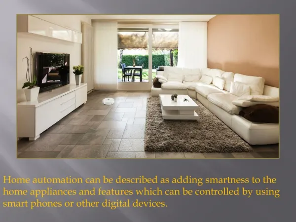
Smart House. Maison Intelligent Members: Steven Bellows, Matthew Marston, Kenneth Nolasco, Brian Sparrow March 26, 2008. The Smart House. Mission: Provide low-cost automated home system Automated systems connected to a central network core: Environment Security Media

E N D
Smart House Maison Intelligent Members: Steven Bellows, Matthew Marston, Kenneth Nolasco, Brian Sparrow March 26, 2008
The Smart House • Mission: Provide low-cost automated home system • Automated systems connected to a central network core: • Environment • Security • Media • Target Market: Private Homeowner • Approximate Prototyping Cost: $825 • Selling Price per Unit: $3000
Technical Objectives • Media • MP3 playback of single zone audio • Play/Stop functions • Volume controls • Previous Song/Next Song functions • Security • Automated door lock • Window break-in detection • Centralized alarm • Environment • Lighting Control • On/Off functions • 30 gradients of dim • Temperature Sensor • -100 to 450 C temperature range • .06250 C resolution
Specifications • Single-Zone Audio Media System • Single “Pleomax” USB-powered speaker • Mp3 Capabilities • fmod sound engine • Simple Playback capabilities • Stop, Play, Previous Song, Next Song • C++ and Windows Programming
Block Diagram Send file pathname Compile List Main Program fmod Play specified mp3 file Return array pointer Return song name FileSearch Sound Output Insert song name
Problems • Multi-zone audio • USB Speakers • Multiplexing • Playback functionality • Rewind, Forward, Pause • Unsupported data types • WAV, MP4 • External iPod source
Access Control and Security … … Network Core Environment Multimedia Security Door Lock Break-in Sensor Alarm System
USB Board Computer USB Cable USB Board … … … Alarm Sensor Door Lock
Alarm … USB Board … Relay USB Board 7 11 Alarm Power Source 3.3V 130mA Alarm
Window Bug … USB Board 7 13 … Window Bug USB Board 7 13 3.3V Power Supply Window Bug
Alarm and window bug designed to work together The alarm is triggered when the Window Bug detects an intrusion The alarm and Window Bug can be manually reset after they are triggered Window Bug triggered at window breaks Window Bug can be tested without breaking a window Manufacturer provides for on the spot testing of the Window Bug Break-in Detection
Door Lock … USB Board 7 15 3.3V Relay 12V 500 mA Lock Power Source
Locking Mechanism • Lock is locked when un-powered • Lock unlocks when a 12V power source is connected • Lock mechanism is controlled by a relay • Relay is controlled by the USB board • User can unlock the door from the user interface • 5 second timer is programmed to automatically relock the door
Security Circuit Computer USB Cable USB Board 7 11 13 15 Copper Wire 3.3V Relay Sensor 3.3V 130mA 12V 500 mA Alarm 3.3V Power Supply Lock Power Supply
Environmental System Temperature System Lighting System
Temperature System • LM76 Series Digital Temperature Sensor • -10oC to 45oC, .0625oC resolution • I2C Bus slave • Altera DE2 Board • Header I/O pins • I2C Bus • Network Core • USB • GUI
Circuit Wall Plug +3.3V Altera DE2 CPU I/O Header Pins Contains Bus Controller and Clock I2C Bus Memory USB
I2C Bus: Serial Communication • Bus master start request • Contains read/write • LM76 internal registers • Transfer to interface registers LM76 writes • Data to I2C Bus • Master sends ACK • Master stop condition • Data in I2C Bus to SDRAM • Sent to network core via USB
Example I2C Timing www.national.com
Lighting System • Network Core • Serial RS-232 • X-10 CM11a Computer Interface • Serial to X-10 PLC • Bit error check • Altera DE2 Board • ADC • On-board LED’s
Circuit RJ-11 PLC 125kHz DB-9 CM11a Network Core .25” Jack Altera DE2 Audio CODEC Data Bus CPU 50MHz Clock Memory LED’s
Transmission • PC sends Header:Code • 2 Bytes • Contains house code, device code, and function code • Interface stores in buffer • Checksum • PC ACK • Interface transmission • Interface ready • Dimming
Sample Transmission www.smarthome.com
Problems • Temperature • I2C controller • USB data output • Testing • 8-SOIC • Lighting • Audio CODEC • Connector • 60Hz timing • Filter
Specifications • Connects computer core to systems • Security • Activewire USB board connections • Audio • Audio/USB cable • Environment • Serially connected to Altera board via X10 • Temperature readings passed through USB
Design: Security System • Security • Data outputted/received via pins • IO0 / Pin 11 : Lock output • IO1 / Pin 13 : Window input • IO2 / Pin 14: Alarm output
ActiveWire Pin Legend www.activewireinc.com
Design: Environmental System • Lighting • Data outputted via RS-232 to X10 • Temperature • Data read via USB from Altera board
Design: Audio System • Single-Zone • Self-contained • Requires Audio/USB wiring • Multi-Zone • USB Speakers • USB drivers, data transfer programming • Multiplexing • Self-contained
Problems • Serial Communication • Windows complexity • X10 encoding • USB Communication • ActiveWire Troubleshooting • Input data latching • Pin directions • Polling/Interrupts • GUI Interfacing
Main Window This is the main window of the GUI that is opened when the program is run. The main window has quick-menu tools to close the program quickly and to read the program information. In the body of the main window are four widgets bound around a fixed body of text. The text will act as a welcome screen as well as to give small instructions to the user. Each of the widgets around the text will act as push buttons to the subdivisions by which they are labeled.
Media The media panel will consist of basic playback controls, song selection controls, current song and progress, and volume control. The basic playback controls will be a Play button to start playback and a Stop button to stop it. The song selection controls will be a Previous Song button and a Next Song button. The Volume controls will be a slider bar with a numeric indicator next to the slider bar for displaying the current volume. The design is currently to have 10 levels of volume. The current song and progress bar will display the song currently playing and it’s percentage of played.
Temperature As of right now, the only output from the temperature facet of the smart home will be a highly accurate, temperature reading. Because of this, only an LCD number displaying the current temperature is made to be on the Temperature window. Until the design is refined to obtain more information, display more content, or increase the functionality, the temperature display box may be implemented permanently in the main window along with other information (date, time, etc.).
Lighting The lighting panel will consist of control of the lighting intensity, current intensity, and a basic on/off input. The control of the light intensity is operated by a scroll bar. The intensity displayed is dependent upon the scroll bar, and since there is no feedback, the lighting system must be initiated with the GUI in order to produce accurate readings. The ON and OFF buttons are simple push buttons to turn the light on or off.
Security The security panel will consist of door unlock, alarm disable, and broken window detection. The door unlock push button will send a signal to the system for a 5 second duration to open the lock. An adjacent text box will give the current status. The alarm in the security circuitry will be disabled from a push button on the GUI interface. The GUI will receive a signal when the network senses the window has been or is broken. As for now, simply a check box that is local to the program.
Problems with Design • Style-sheet formatting • Coding rules, hierarchies, and order • Widgets • Development , integration • Functionality • Difficulties • Graphics / Aesthetics • Import sizes, formats
Demonstration Plan • Environment • Dimmer switch control through LEDs • Temperature display • Security • Remote lock control • Break-in detection / alarm activation
Demonstration Plan Cont. • Audio • Mp3 playback and control • Network Core Programming • Successful computer control • GUI • Comprehensive interface