Download
1 / 18
180 likes | 335 Views
Partial Electronic and Ionic Conductivities of Nanocrystalline Ceria Ceramics. Sangtae Kim , Jürgen Fleig, Joachim Maier. Max Planck Institute for Solid State Research Stuttgart, Germany. IMSPEMAS. Warsaw, Poland. September 26, 2003. Contents. Introduction

E N D
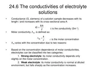
Partial Electronic and Ionic Conductivities of Nanocrystalline Ceria Ceramics Sangtae Kim, Jürgen Fleig, Joachim Maier Max Planck Institute for Solid State Research Stuttgart, Germany IMSPEMAS Warsaw, Poland September 26, 2003
Contents Introduction -Different conduction pathways in polycrystalline ceramics and their superposition -Bricklayer model -Core-space charge model for grain boundary Detectability in impedance spectroscopy -Highly conductive grain boundary -AgBr bicrystal -AgCl polycrystalline ceramics -AgCl polycrystalline ceramics with microelectrodes -Highly blocking grain boundary -SrTiO3 polycrystalline ceramics with microelectrodes -SrTiO3 bicrystal -Highly selective grain boundary for partial electronic and ionic conduction -nanocrystalline CeO2 ceramics -Quantitative analysis based on space charge models
For quantitative analysis Space charge zones (sc) Grain boundary (gb) 2l dg z z y y Grain boundary core (gc) Bulk dgc= 2b x x Bricklayer model Equivalent circuit Core-space charge model Effective complex conductivity • Assumption: • cubic-shaped grains of identical size and property • identical, homogeneous grain boundaries J. Jamnik, et al., Solid State ionics, 75, 51 (1995) J. Maier, Ber. Bunsenges. Phys. Chem., 90, 26 (1986) Conduction in polycrystalline electroceramics Electroceramics for practical applications are polycrystalline forms. Importance of understanding grain boundary effects relative to the bulk effect on total conduction Impedance analysis
96oC w/o annealing 190oC 1h 300oC 1h annealing Highly conductive space charge zones with blocking grain boundary core: AgBr bicrystal J. Maier, Ber. Bunsenges. Phys. Chem., 90, 26 (1986)
annealing Highly conductive space charge zones with blocking grain boundary core: AgCl polycrystalline ceramic J. Maier, Ber. Bunsenges. Phys. Chem., 90, 26 (1986)
inverse resistance in 10-9S/cm 7.2 25 mm 23.9 34.6 7.8 7.5 8.4 11.8 5.4 5.1 7.9 8.9 Microelectrode on grain Microelectrode on grain boundary 9.0 9.5 64.1 31.7 66.1 31.7 40.5 100 75 W G / 50 m i Z - 1 Hz 25 1 Hz on grain on grain boundary 0 0 25 50 75 100 125 150 175 200 W Z / G re J. Fleig, J. Maier, Solid State Ionics, 86-88, 1351 (1996) Highly conductive space charge zones: AgCl polycrystalline ceramic - Microelectrodes Measurement principle
+ Gouy-Chapman Profile Ag + Ag Ag-vacancy Ag-vacancy + V V Ag Ag Ag concentration concentration V V Ag + Ag Ag V V Ag Ag V V V V Ag V Ag Ag V Ag V V V Ag V + V V Ag Ag Ag Ag Ag Ag Ag Ag V V V V V V V V V Ag Ag Ag V Ag Ag Ag Ag Ag Ag Ag + Ag x x 2l 2l gb core space charge zone space charge zone + Ag space charge potential = 300 mV Charge carrier accumulation in space charge zones
a W / b im -Z 2e+9 a 1e+9 0 0 1e+9 2e+9 3e+9 4e+9 b 0 V 2e+9 W W 4e+9 0,2 V / / b m m 0,6 V i i Z Z 1,0 V - - 2e+9 1e+9 0 0 0 2e+9 4e+9 6e+9 8e+9 1e+10 W 0 1e+9 2e+9 3e+9 4e+9 / Z real W Z / re Blocking space charge zones: Fe-doped SrTiO3 polycrystalline ceramic: Microelectrodes Measurement principle S. Rodewald, et al., J. Am. Ceram. Soc., 84, 521 (2001)
T = 598K zero bias 200 mV P = 105 Pa O 400 mV 2 x 600 mV 2nm Blocking space charge zones: Fe-doped SrTiO3 bicrystal S5 tilt grain boundary: [Fe] = 21018cm-1 3 5 10 x 3 4 10 x W 3 3 10 x -Im Z / 3 2 10 x 20 Hz 1 MHz 3 1 10 x x x x x x x x x x x x x x x x x x x x x x x x x x x x x x x x x x x x x x x x x x x x x x 0 3 3 3 3 0 1 10 3 10 5 10 7 10 x x x x Re Z / W
Defect concentration space charge zone space charge zone ' Fe Ti Vo•• Mott-Schottky Profile h• l* l* x 2nm mean space charge potential 650 mV Charge carrier depletion in space charge zones
Nanocrystalline CeO2 Nanocrystalline CeO2 For intrinsic e´ e´ Vo•• Defect concentration Vo•• l l x bulk gc bulk S. Kim, J. Maier, J. Electrochem. Soc, 149, J73 (2002) Space charge effects on the partial electronic and ionic conductivity of nanocrystalline CeO2 ceramic Defect equilibrium in CeO2 Mixed conductor
Gd´ Gd´ Vo•• Vo•• e´ e´ x x l* l* l* l* Pt/n-CGO/YSZ/Pt R1 + R2 ~ Rdc t ~ ion Ionic conductivity behavior of nanocrystalline CeO2 ceramic: 0.15 mol% Gd-doped CeO2 S. Kim, J. Maier, J. Electrochem. Soc, 149, J73 (2002)
A´ Vo•• e´ x l* l* Pt|nano-CeO2|Pt Pt|nano-CeO2|YSZ|Pt e = 33 1.9 eV S. Kim, J. Maier, J. Electrochem. Soc, 149, J73 (2002) Electronic conductivity behavior of nanocrystalline CeO2 ceramic: Nominally pure CeO2
Model For z1 = -z2 For 2z1 = -z2 For z1 = -2z2 a b c 1 1 2 d e 3 f 2 1 3 Gouy- Chapman 1 2 1 g h i 1 1 2 3 3 1 2 2 2 3 j k l 1 2 3 3 1 2 m 3 2 Mott- Schottky 2 1 n o p 1 1 3 1 3 Combined 1 1 3 3 2 2 0 0 0 3 2 2 2 Effective defect concentration in the space charge zone S. Kim et al., Phys. Chem. Chem. Phys., 5, 2268 (2003) 1: accumulated defect 2: depleted defect 3: dopant
Quantitative analyses of pO2 and T dependence forr based on Mott-Schottky model: Gd-doped nano-CeO2 Quantitative analyses Gd´ Vo•• 0 e´ x l* l* Mott-Schottky situation Space charge potential for Experimental results J.Fleig et al., J. Appl. Phys., 87(5), 2372 (2000) Concentration profile in n-CGO
Quantitative analyses of pO2 and T dependence fors||based on Mott-Schottky model: Nominally pure nano-CeO2 Quantitative analyses A´ Vo•• -1/4 e´ x l* l* Mott-Schottky situation Lower impurity concentration n-CeO2-x e = 33 - 2.37§ eV + 0.4 eV - 1.97 eV - 1.9 eV § Tuller and Nowick, J. Electrochem. Soc., 122, 255 (1975) Experimental results -
Summary Not only highly resistive but also highly conductive grain boundary effects are demonstrated with respect to detectability of impedance spectroscopy In ceria, grain boundary becomes highly selective for electronic and ionic conduction. This can be quantitatively explained based on the space charge models.
Quantitative analysis ® numerical finite element calculations microelectrode on grain boundary potential distribution more complicated numerical analysis grain boundary conductance ® » -11 s 4·10 1/ W (w · ) microelectrode on grain potential distribution Most potential drops close ® to microelectrode R as for microelectrode on single crystal ® method to obtain bulk conductivity » s W 8·10 1/ cm -9 bulk