Download
1 / 71
1.08k likes | 6.16k Views
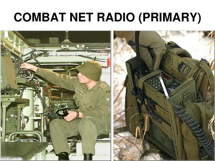
COMBAT NET RADIO (PRIMARY). AN/PRC-522 (RAD B) Manpack. AN/VRC-513 (V)1 (RAD A) Low power vehicle Installation. AN/VRC-513 (V)2 (RAD A+) High power vehicle Installation. COMBAT NET RADIO (PRIMARY) CONFIGURATIONS. AN/PRC-522 COMPONENTS. Radio Set, RT-5121/U. Handset, H-5036/U.

E N D
AN/PRC-522 (RAD B) • Manpack. • AN/VRC-513 (V)1 (RAD A) • Low power vehicle Installation. • AN/VRC-513 (V)2 (RAD A+) • High power vehicle Installation. COMBAT NET RADIO (PRIMARY) CONFIGURATIONS
AN/PRC-522 COMPONENTS • Radio Set, RT-5121/U. • Handset, H-5036/U. • 2 whip antennas. • Harness assembly. • Headset-Microphone, H-5034/U. • 2 Batteries, BB-503/PRC-522.
RT-5121/U CHARACTERISTICS • Medium-powered. • Very High Frequency (VHF).. • Frequency Modulated (FM). • 2 carrying handles. • Hold-Up battery (HUB). • Located in the base of the radio. • Retains Time-of-day, fill data, frequencies.
RT-5121/U CHARACTERISTICS • Frequency Range. • 30 MHz to 107.975 MHz. • Channel Spacing (Frequency Separation). • 25 kHz. • Total Channels (Number of Frequencies). • 3120.
RT-5121/U CHARACTERISTICS • Operating Features: • Fixed Compatible; • Fixed Super; • Frequency Hopping (As an ECCM measure); • 100 hops/second. • Radio Rebroadcast (RRB); • Voice and Data; • Secure and Non-Secure; and • Economize Mode.
RT-5121/U CHARACTERISTICS • Power Output (Manpack). • Low - 100 mw. • Medium - 4 W. • Preset (programmable) Channels - 8. • Operating Temperature. • -40°C to +48°C. • Weight - 4.5 Kg (RT only).
2.4 M WHIP ANTENNA • 2.4 meters long. • 8 sections with an elastic cord through the center. • Flexible base for profile adjustment.
1.2 M WHIP ANTENNA • 1.2 meters long. • 1 flexible section. • Same flexible base as the 2.4 meter antenna for profile adjustment.
HEADSET-MICROPHONE H-5034/U • Lightweight. • Held in place by straps. • PTT switch located on the clothing clip. • Single earpiece. • Single boom microphone. • Used on either left or right side of head.
HANDSET H-5036/U • Molded high impact body. • Single earphone. • Single microphone. • Activated by side mounted PTT switch.
CARRYING HARNESS • Stores and supports • RT-5121/U. • the 2 whip antennas. • headset and handset. • the 2 batteries. • an operator card.
BATTERY BB-503/PRC-522 SAFETY • The BB-503/PRC-522 has a pressure release valve located on the end of the battery where the spare fuse holder is. • allows air to escape if there is pressurebuilds up inside the battery.
BATTERY BB-503/PRC-522 • Rechargeable Nickel Cadmium. • Two connecting thumbscrews. • Provides 12 Vdc.
BATTERY BB-503/PRC-522 • Requires a 6.3 A fuse (will not work without). • 2 spares in well in side of battery. • Weight - 2.5 kg. • Operating Temperature: -40°C to +48°C.
BATTERY BB-503/PRC-522 • TX:RX:STANDBY Ratio of 1:1:8 • +20° - 10 hours of life. • -20° - 6 hours of life. • -30° - 5 hours of life.
888888 88 RT-5121/U Display and Keypad
AN/PRC-522 ASSEMBLY • 4 steps: • Attach battery to RT-5121/U; • Place the spare battery, then the RT with the attached battery into the harness; • Attach the handset; and • Attach the whip antenna.
AN/PRC-522 DISASSEMBLY • Reverse of the assembly: • Remove the antenna and store it in the ancillary pouch; • Remove the handset and store it in the ancillary pouch; • Remove the spare battery and then the transceiver with attached battery; and • Disconnect the battery from the transceiver. *NOTE* Place all protective caps on the transceiver.
OPERATOR MAINTENANCE The systematic care and inspection of equipment to prevent failure and downtime.
OPERATOR MAINTENANCE RT-5121/U • Check for cracks, holes, or dents; • Check for dirt, paint, oil, or other foreign material; • Check for dents, punctures, or warped areas; • Inspect all knobs and switches for mechanical integrity.
OPERATOR MAINTENANCE WHIP ANTENNAS • Inspect for breaks or strains. • Replace as necessary.
OPERATOR MAINTENANCE HEADSET-MICROPHONE AND HANDSET • Check for damage and dirt. • Check PTT switch and cables.
OPERATOR MAINTENANCE HARNESS • Inspect for signs of physical damage, wear, and completeness.
OPERATOR MAINTENANCE BATTERY BB-503/PRC-522 • Inspect for dented, punctured and warped areas; • Ensure the 6.3 A fuses are installed; • Check for loose or missing screws; • Check for leaks and corrosion.
OPERATOR MAINTENANCE CLEANING • Use a clean, lint-free cloth. Ensure all dirt is removed from connectors, switches, and terminals.
OPERATIONAL READINESS TEST (ORT) • To ensure the AN/PRC-522 is functional after assembly: • perform the power-on procedure; and • then conduct a radio check with a serviceable transceiver.
POWER-ON PROCEDURE • 3 steps: • Set CHANNEL switch to desired channel; • Set CRYPTO switch to desired mode of operation; and • Turn the ON/OFF switch to on (rotate clockwise not passed S Off).
POWER-ON PROCEDURE • As long as the radio has been turned off for more than 3 seconds, it will enter the power-on built-in test (BIT). • “888888 88” appear in the display for 2 secs. • No fault - the existing frequency, transmission mode, and power level is shown in the display. • Fault - alarm sounds and a four digit BIT Error Code will appear.
TABLE OF PROBABLE FAULTS • Column 1 - description of the fault. • Column 2 - probable cause. • Column 3 - Corrective action to be taken.
BIT ERROR CODES • Press the to scroll through the list until the word “End” is shown. • Press the T key at any time to exit the list and return to normal display (frequency, transmission mode, power level).
NOTE • Transceiver does NOT transmit during the Power-On BIT. • transmit module is not tested. • Display will timeout after 11.5 seconds. • a hyphen alternatesbetween the left and the right side of the display.
OPERATIONAL READINESS TEST • 3 steps (Power-On Procedure): • Set CHANNEL switch to desired channel; • Set CRYPTO switch to desired mode of operation; • Turn the ON/OFF switch to on (rotate clockwise not passed S Off); and • Conduct a radio check to complete the Operational Readiness Test.
AUDIBLE/VISUAL INDICATORS AND ALARMS • There are 9 audible indicators and alarms. • Error Tone. • A continuos alternating 2 tone alarm with no pause in between. • Incorrect entry during programming. • Operation of a hopping net with 2 transceivers set to Master (H). • Hopset OTAR reception error.
AUDIBLE/VISUAL INDICATORS AND ALARMS • There are 9 audible indicators and alarms. • Hailing Tone / Plain Text Cue • A series of pips lasting for 10 seconds. • Hailing Tone - when operating in Frequency Hopping mode and receiving a Fixed Compatible transmission. • Plain Text Cue - In Cipher Text VINSON mode, when receiving a Plain Text message.
AUDIBLE/VISUAL INDICATORS AND ALARMS • There are 9 audible indicators and alarms. • Advanced Time-Of-Day Warning. • A series of pips lasting for 5 seconds and voice can still be heard over the pips. • Operation of a hopping net and an outstation sends a transmission with an Advanced TOD, the Master will receive this warning.
AUDIBLE/VISUAL INDICATORS AND ALARMS • There are 9 audible indicators and alarms. • Unready Tone. • A series of fast pips. • when operating in Frequency Hopping mode, and the transceiver is synchronizing and not ready to pass traffic. • when operating in Selective Communication mode, all unselected transceivers will receive this tone.