Download
1 / 35
350 likes | 494 Views
CPU Design for Multiple Clock Cycles per instruction {CPI > 1}. Be able to explain how an instruction is executed and the concept of datapaths and control. Where we are headed. Single Cycle Problems: clock cycle determined by instruction that takes the longest time

E N D
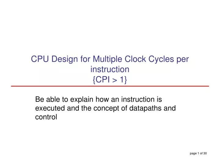
CPU Design for Multiple Clock Cycles per instruction {CPI > 1} Be able to explain how an instruction is executed and the concept of datapaths and control
Where we are headed • Single Cycle Problems: • clock cycle determined by instruction that takes the longest time • what if we had a more complicated instruction like floating point? • wasteful of area • each functional unit is used only once per cycle (per instruction) • it may be possible to reduce functional units • One Solution: • use a “smaller” cycle time • have different instructions take different numbers of cycles • a “multicycle” datapath
Multiple cycle data path • Divide the instruction into components • Choose the clock cycle to accommodate the longest component • We need some balance between the components to reduce wastage • Same approach carries over to pipeline architectures • Every instruction divided into • Instruction fetch • Instruction decode and operand fetch • Execution, memory address computation or branch completion • Memory access or complete R-type instruction • Memory read completion • Work towards fewer components • Must we have a PC - Adder and an ALU – what if these are in different cycles? • Single memory for instructions and data • May need buffers (registers) for temp storage, e.g Instruction Register • Controls will be more complicated – determined by cycle and op code
Review: finite state machines • Finite state machines: • a set of states and • next state function (determined by current state and the input) • output function (determined by current state and possibly input) • We’ll use a Moore machine (output based only on current state) Ó1998 Morgan Kaufmann Publishers
Multicycle Approach • Break up the instructions into steps, each step takes a cycle • balance the amount of work to be done • all cycles are of equal length • how to fix the length of a cycle? • restrict each cycle to use only one major functional unit • At the end of a cycle • store values for use in later cycles (easiest thing to do) • introduce additional “internal” registers
Multiple Cycle Approach • Single memory – instruction + data • One ALU, instead of ALU + 2 Adders • Eliminating adders saves cost – what are we adding? • Add temp store registers at the functional unit output – save for use in later cycle • MDR, IR are added. Both values are indeed in the same clock cycle • A, B, ALUOut are added • Registers and multiplexers are less costly than adders • Overall savings!
P C 0 0 I n s t r u c t i o n R e a d M M A d d r e s s [ 2 5 – 2 1 ] r e g i s t e r 1 u u x x R e a d A I n s t r u c t i o n R e a d Z e r o M e m o r y 1 d a t a 1 1 [ 2 0 – 1 6 ] r e g i s t e r 2 A L U A L U A L U O u t 0 M e m D a t a R e g i s t e r s r e s u l t I n s t r u c t i o n W r i t e M R e a d [ 1 5 – 0 ] r e g i s t e r B u 0 d a t a 2 I n s t r u c t i o n W r i t e x [ 1 5 – 1 1 ] M I n s t r u c t i o n 4 1 W r i t e d a t a 1 u r e g i s t e r d a t a 2 x 0 I n s t r u c t i o n 3 [ 1 5 – 0 ] M u x M e m o r y 1 1 6 3 2 d a t a S h i f t S i g n r e g i s t e r l e f t 2 e x t e n d • Jump and Branch – PC update requires special consideration. 3 possibilities. • PC = PC + 4 during IF. Store directly into PC. • ALUOut contains the branch target when it is computed. • Pseudodirect address for jump instruction.
Five Execution Steps • Instruction Fetch • Instruction Decode and Register Fetch • Execution, Memory Address Computation, or Branch Completion • Memory Access or R-type instruction completion • Write-back step INSTRUCTIONS TAKE FROM 3 - 5 CYCLES! Ó1998 Morgan Kaufmann Publishers
Step 1: Instruction Fetch • Use PC to get instruction and put it in the Instruction Register. • Increment the PC by 4 and put the result back in the PC. • Can be described succinctly using RTL "Register-Transfer Language" IR <= Memory[PC]; PC <= PC + 4;Can we figure out the values of the control signals? • Assert MemRead & IRWrite, IorD=0 (PC is source address) • PC+4: ALUSrcA=0; ALUSrcB=01; ALUOp=00 • Storing in PC: PCSource=00, Assert PCWrite What is the advantage of updating the PC now? • Value computed in parallel with Instruction Access.
Step 2: Instruction Decode and Register Fetch • Read registers rs and rt in case we need them • Compute the branch address in case the instruction is a branch {Potentially wasted effort vs saving cycles} • RTL:A <= Reg[IR[25:21]];B <= Reg[IR[20:16]];ALUOut <=PC+(sign-extend(IR[15:0])<< 2); • We aren't setting any control lines based on the instruction type • instruction is being decoded in the control logic – we do not know the type before ID & RF starts
Step 3: Execution, Compute Effective Address or Branch Completion • ALU is performing one of three functions, based on instruction type • Memory Reference: ALUOut <= A + sign-extend(IR[15:0]); • R-type: ALUOut <= A op B; • Branch: if (A==B) PC <= ALUOut; • Jump: PC <= PC[31:28]||(IR[25:0]<<2)
Step 4: R-type or memory-access • Loads and stores access memory MDR <= Memory[ALUOut]; or Memory[ALUOut] <= B; • R-type instructions finish Reg[IR[15:11]] <= ALUOut;The write takes place at the end of the cycle on the falling edge
Step 5: Write-back step • Load Reg[IR[20:16]]<= MDR; What about all the other instructions? Ó1998 Morgan Kaufmann Publishers
Action for R-type Action for memory-reference Action for Action for Step name instructions instructions branches jumps Instruction fetch IR <= Memory[PC] PC <= PC + 4 Instruction A <= Reg [IR[25:21]] decode/register fetch B <= Reg [IR[20:16]] ALUOut <= PC + (sign-extend (IR[15-0]) << 2) Execution, address ALUOut <= A op B ALUOut <= A + sign-extend if (A ==B) then PC <= PC [31:28] computation, branch/ (IR[15:0]) PC <= ALUOut ||(IR[25:0]<<2) jump completion Memory access or R-type Reg [IR[15:11]] <= Load: MDR <= Memory[ALUOut] completion ALUOut or Store: Memory [ALUOut] <= B Load: Reg[IR[20:16]] <= MDR Memory read completion Summary:
Simple Questions • How many cycles will it take to execute this code? lw $t2, 0($t3) lw $t3, 4($t3) beq $t2, $t3, Label #assume not add $t5, $t2, $t3 sw $t5, 8($t3)Label: ... • What is going on during the 8th cycle of execution? • In what cycle does the actual addition of $t2 and $t3 take place? lw: 5 cycles; beq: 3 cycles; add: 4cycles; sw: 4 cycles lw: IF, ID, MemAddrCompute, MemAccess, WB
Implementing the Control • Value of control signals is dependent upon: • what instruction is being executed • which step is being performed: clock cycle related • Use the information we’ve accumulated to specify a finite state machine • specify the finite state machine graphically, or • use microprogramming • Implementation can be derived from specification
High Level View of Control System Fig 5.31/Third Edition
IF & ID cycles Fig 5.32/Third Edition
FSM for Memory-Reference Instruction Fig 5.33/Third Edition
R-type Instruction Fig 5.34/Third Edition
Branch & Jump Fig 5.36/Third Edition
I n s t r u c t i o n d e c o d e / I n s t r u c t i o n f e t c h r e g i s t e r f e t c h 0 M e m R e a d 1 A L U S r c A = 0 I o r D = 0 A L U S r c A = 0 I R W r i t e A L U S r c B = 1 1 S t a r t A L U S r c B = 0 1 A L U O p = 0 0 A L U O p = 0 0 P C W r i t e P C S o u r c e = 0 0 ) ) ' e Q p ) y t ' - E R J B ' = ' p = O = ( ) ' p W p M e m o r y a d d r e s s S ' O = B r a n c h O J u m p ( p O ( c o m p u t a t i o n ( r o E x e c u t i o n c o m p l e t i o n ) c o m p l e t i o n ' W L ' = p O 2 6 8 9 ( A L U S r c A = 1 A L U S r c A = 1 A L U S r c B = 0 0 A L U S r c A = 1 P C W r i t e A L U S r c B = 1 0 A L U O p = 0 1 A L U S r c B = 0 0 P C S o u r c e = 1 0 A L U O p = 0 0 P C W r i t e C o n d A L U O p = 1 0 P C S o u r c e = 0 1 ( O ) p ' = W ' S L ' W ' = ) p M e m o r y M e m o r y O ( a c c e s s a c c e s s R - t y p e c o m p l e t i o n 3 5 7 R e g D s t = 1 M e m R e a d M e m W r i t e R e g W r i t e I o r D = 1 I o r D = 1 M e m t o R e g = 0 W r i t e - b a c k s t e p 4 R e g D s t = 0 R e g W r i t e M e m t o R e g = 1 Graphical Specification of FSM How many state bits will we need? Ó1998 Morgan Kaufmann Publishers
Finite State Machine for Control • Implementation: Ó1998 Morgan Kaufmann Publishers
PLA Implementation • If I picked a horizontal or vertical line could you explain it? Ó1998 Morgan Kaufmann Publishers
m n ROM Implementation • ROM = "Read Only Memory" • values of memory locations are fixed ahead of time • A ROM can be used to implement a truth table • if the address is m-bits, we can address 2m entries in the ROM. • our outputs are the bits of data that the address points to.m is the "height", and n is the "width" 0 0 0 0 0 1 1 0 0 1 1 1 0 0 0 1 0 1 1 0 0 0 1 1 1 0 0 0 1 0 0 0 0 0 0 1 0 1 0 0 0 1 1 1 0 0 1 1 0 1 1 1 0 1 1 1 Ó1998 Morgan Kaufmann Publishers
ROM Implementation • How many inputs are there? 6 bits for opcode, 4 bits for state = 10 address lines (i.e., 210 = 1024 different addresses) • How many outputs are there? 16 datapath-control outputs, 4 state bits = 20 outputs • ROM is 210 x 20 = 20K bits (and a rather unusual size) • Rather wasteful, since for lots of the entries, the outputs are the same Ó1998 Morgan Kaufmann Publishers
ROM vs PLA • Break up the table into two parts — 4 state bits tell you the 16 outputs, 24 x 16 bits of ROM — 10 bits tell you the 4 next state bits, 210 x 4 bits of ROM — Total: 4.3K bits of ROM • PLA is much smaller — can share product terms — only need entries that produce an active output — can take into account don't cares • Size is (#inputs ´ #product-terms) + (#outputs ´ #product-terms) For this example = (10x17)+(20x17) = 460 PLA cells • PLA cells usually about the size of a ROM cell (slightly bigger) Ó1998 Morgan Kaufmann Publishers
Processor design review • Single clock cycle instructions (CPI = 1) • Clock cycle is longer • Designing for the worst case • Multiple clock cycles per instruction • Divided each instruction into components • Tried for balance among the functions • Better performance ? • Some instructions take a little longer. • Some instructions take fewer cycles than others. • On the average we have improved performance
Design process • Determine datapath requirements • Pick an instruction (sometimes one instruction can represent an entire class, e.g. R-type) • Determine the datapath required for execution of the instruction • Determine the controls required for the instruction • Find the data path required for all the instructions • Find the shared path requirements • One approach: develop an input – output matrix • Find destinations that have more than one input • Insert multiplexers where necessary • Determine control requirements • CPI = 1 • Controls are controlled by opcode • CPI > 1 • Controls are controlled by opcode and system state • Finite State Machine • Hardwired (PLA) or Software (Microprgrammed) implementation
Interrupts, exceptions • Interrupt vs exception • Interrupt: External – I/O device request • Exception: Internal – OS calls, arithmetic overflow • Interrupts are external hardware events • Raise an interrupt (hardware) • Wait to complete the current instruction • Determine the source of the interrupt • Save the return address • Transfer to relevant Interrupt Service Routine • Save the registers that may change • Execute the program • Can this be interrupted? • Restore the registers • Return to execution of the program
Exceptions • Exceptions are software driven • Overflow in an arithmetic instruction • Memory access yields an undefined instruction • MIPS exception handling • Registers • Stores address of the problem instruction in EPC – Exception PC • Store the cause of the exception in the Cause Register • Cause low order bit = 0 (undefined instruction) • Cause low order bit = 1 (arithmetic overflow) • Additional control signals – IntCause, EPCWrite and CauseWrite • Transfer control to specified location in OS • OS terminates program or continues processing
Multicycle Datapath with Exception Handling Fig 5.39/Third Edition
Exception handling Fig 5.40/Third Edition