Download

1 / 30
300 likes | 350 Views
The Preassembling Installation Survey & Alignment. Accelerator Center of IHEP Qu Huamin 2006 / 4 / 27. 1. The Preassembling and Prealignment.

E N D
The Preassembling Installation Survey & Alignment Accelerator Center of IHEP Qu Huamin 2006/4/27
1. The Preassembling and Prealignment • Because the double rings are installed in the existing tunnel of BEPC, so the space in the tunnel is very restrained, and the time of BEPCII installation is very strict, so we decided to preassemble the dipole, quadruple, sextuple, BV magnet, vacuum chamber, and so on, in a girder. The total weight is about 15T. • Align and adjust every component in the girder to let their location arrive at the required precision. Then, they were wholly moved to the BEPC tunnel to install. • We will adjust the girder by survey and alignment, every component will achieve the installation precision that the accelerator physics required. So BEPCII installation time will be greatly shorten.
The Preassembly Prealignment Plan • Base on the new CPM scheme of BEPCII storage rings The time of the preassembly prealignment: 2005/08/01~2006/07/27 • The sequence of the preassembly prealignment: According to the sequence of installing the components in the tunnel. • The preassembly prealignment of each cell includes the transportation and installation of every kinds of magnets and girders, the fiducializing of magnets, surveying and adjusting of the magnets, disassembly the core and water hose of the magnets, the transportation and installation of vacuum system, reinstalling the core and water hose of magnets, carefully adjusting the magnets and the vacuum system, fixing the magnets and the vacuum system to the girders, the lifting and transporting the cell, and so on.
In order to complete the task of the preassembly prealignment on time, we decided the ration which the 2 preassembly prealignment cells are finished in 4~5 days based on the actual fact and the experiments. • Up to now, 52 preassembly prealignment cells have been completed according to the preassembly prealignment plan. • We anew began to preassemble and prealign on Dec. 20, 2005. We will complete all 84 preassembly prealignment cells on July 20, 2006.
The plan and lists of components for the preassembly prealignment
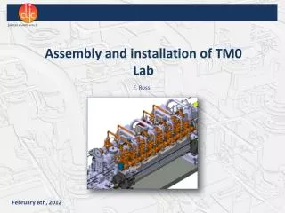
Figure 2-1 The picture of the preassembly and prealignment cell
Figure 2-2 The picture of the preassembly and prealignment cell
2. Installation of BEPCII storage rings • We have completed to mark the beam line on the floor after surveying the tunnel network. The precision is about 1mm. • We have completed to drill holes on the floor in the tunnel in order to fix each cell to the floor, the precision is about 2mm.
North • In order to insure the installation plan, we install the components according to regions (R4, R3, R2, R1, RF region, IR region, see figure 6). South Figure 6 BEPCII storage ring layout
The detailed requirements are as fellows: (1) Besides RF cavity and all components of IR are installed at any moment according to the demand, the installation sequence of all components is R3 and R4 regions ( they are installed at the same time in the two regions, respectively ) the magnets in the east and west injection regions R2 region R1 region the vacuum chambers in the east and west injection regions RF region. (2) Besides the IR components (R3Q03~R4Q03), the other are transported into the tunnel from the second hall, all components is orderly installed from south to north in the tunnel. (3) The adjusting devices and the fixing plate is installed after the cell is transported to the second hall. Then it is placidly moved to the installation position by the gas cushion. (4) The rough installation precision of every cell is required to arrive at 2mm.
(5) Remove the fixing devices of the dipole magnet and QS sharing plate in the cell. (6) Install the cables of BPM, vacuum pumps, power supply and the water hoses of every magnet and vacuum system in the cell. (7) Survey and alignment (7.1) Check the correlation of the dipole, quadruple, sextuple and BV magnet after rough installation of each cell. If their correlation occurs to change and don’t satisfy the requirement, we will readjust them. (7.2) Survey the magnets in the cell, and adjust girder to let all magnets arrive at the physics required installation precision. (7.3) Measure the adjacent flanges of vacuum chamber to judge if they are satisfied to install RF bellows (remarks: the transverse offset is less than 1mm, the angle is less than 1° between the the adjacent flanges). If they aren't, readjust the vacuum chamber.
(8) Install RF bellows by using the special tools. (9) Test water and power after all components in the region are fully installed, then test vacuum. (10) Measure the tunnel controling network again after all components of BEPCII storage rings are wholly installed, then smooth all magnets. • Up to now, the 20 cells have been installed in R3 region, 9 cells have been installed in R4 region. • We decided 4~5 cells to be installed in the tunnel each week, so all 84 cells will be installed to the tunnel on July 22, 2006. • We will complete to install all other components on Aug. 20 according to the new installation plan.
By measuring the magnets of the cell in several days, we found that the uneven sedimentation of the floor is occurred during installation of cells, namely the aligning precision of the magnets was affected by the latter installation cells, so we have stopped to install RF bellows. • Now we are observing and studying the uneven sedimentation of the floor by installing the exact hydraulic level system, we will begin to install RF bellows after it is change to be small.
Figure 6 The picture of the cell supported by air cushion in the tunnel
Figure 7-1 The picture of moving the cell by air cushion in the tunnel
Figure 7-2 The picture of moving the cell by air cushion in the tunnel
Figure 8 The picture of putting the foot screws on the tunnel floor
Figure 9 The picture of installing the cell on the tunnel floor
Figure 11 The picture of the double rings installed in the R3
3. The survey and alignment for the BEPCII storage rings Tolerable displacements for storage ring magnets (components) defined by the accelerator physics The circumference of storage rings cannot deviate from its design value by more than 5mm; the difference between two rings has to be set within 4mm.
We set up that the horizontal controlling network and the elevation controlling network which have 37 points for each taking account of the peculiarity and requirement of the survey and alignment of the BEPCII double rings. • We have measured the controlling networks conveniently and accurately because of specifically dealing with the networks and avoiding away crowd area. Figure 12 The controlling network of the BEPCII storage ring
We have measured the controlling network by using the total station instrument, the laser track and the level instrument. The reversely radial precision of the adjacent points is 0.08mm, the absolutely radial precision is 0.19mm. • According to the component installation tolerance of the BEPCII storage rings which accelerator physics gives, the scheme of the component fiducializing, the preassembling and aligning, and the tunnel survey and alignment has been studied and decided. The detailed tolerance analysis has been made, and the total tolerance has been reasonably distributed to the six taches in course of the component installation. so the total tolerance of the component installation is successfully limited in the range of physics requirement.
Figure 13 The picture of the aligning and adjusting the cell installed in the R3
After the cell is installed, we check the correlation of the dipole, quadruple, sextuple and BV magnet. If their correlation occurs to change and don’t satisfy the requirement, we will readjust them. • Survey and align the magnets in the cell, and adjust girder using the adjusting device by controlling the step motors to let all magnets arrive at the physics required installation precision. • In order to arrive at the installation tolerance of the BEPCII storage rings which accelerator physics gives, We will smooth all magnets after all components of the BEPCII storage rings is installed.
4. Summary • Because of good organization and management, the task of the preassembling and prealignment will be completed on 2006/07/20. • The space in the BEPCII tunnel is very restrained, it is very difficult to install every component, but it is very carefully studied beforehand, so it can be completed on 2006/08/20. • The uneven sedimentation is occurred during installation, survey and alignment has to repeat in many times. When the vacuum chambers are connect, it is difficult to survey and alignment because of the restriction of RF bellows, so the task of survey and alignment is onerous. Thanks for your attentions !