Download
1 / 16
160 likes | 313 Views
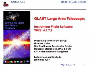
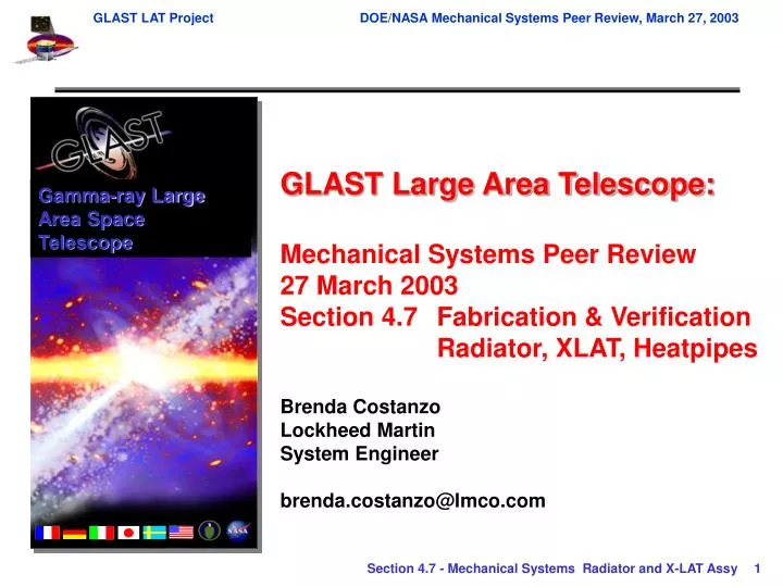
Gamma-ray Large Area Space Telescope. GLAST Large Area Telescope: Mechanical Systems Peer Review 27 March 2003 Section 4.7 Fabrication & Verification Radiator, XLAT, Heatpipes Brenda Costanzo Lockheed Martin System Engineer brenda.costanzo@lmco.com. Obtain Facesheet Material.

E N D
Gamma-ray Large Area Space Telescope GLAST Large Area Telescope: Mechanical Systems Peer Review 27 March 2003 Section 4.7 Fabrication & Verification Radiator, XLAT, Heatpipes Brenda Costanzo Lockheed Martin System Engineer brenda.costanzo@lmco.com
Obtain Facesheet Material Purchasing Shear Inspect Clean, Etch & Prime N/C Machine Inspection/Test Manufacturing Inspect Verify Flight Materials Log Flight Materials Obtain Remaining Flight Materials Radiator Fabrication (1 of 2) Inspect Thermal Bond Visual Bond Pipes To OB Facesheet Assemble Panel and Bond Machine Transfer Datums Fit Check Core Verify Cure Profile Process Samples To Lab Inspect Holes w/ Pins Prep and Install Inserts & Spools Inspect Inserts & Spools Bond IB Doublers RT Cure CMM Inspect Geometry Inspect Doublers Bond OB Doublers AC Cure Verify Cure Profile Bond Top Edge Closure A
Bond Reservoir Supports Inspect Reservoir Supports Fit Check Reservoir Bushings Machine Bushings Inspect Bushings A Install Reservoir Bushings Inspect Bushings Apply Edge Closure Tape Structural Testing Thermal Testing Final Cosmetic Damage Map Apply Thermal Blanket Apply Blanket Velcro Radiator Fabrication (2 of 2) • Notes • All panel moves require: inspection documentation of panel for damage; packaging for • transport; and flight approved move procedures. • No outside storage. • Qualified flight transportation personnel and equipment.
M & P Plan, EEE Parts • M & P Plan submitted to SLAC (GLS00018-2, dated 1 Feb 2003) • EEE Parts • Heaters: Minco Kapton Foil Heaters per GSFC S-311-P-079 • Thermistors: YSI Thermistors per GSFC S-311-P-18 • RTDs: Rosemount PRT per GSFC S-311 • Solid State Thermostats: Micropac 52372”O” • Submitted to SLAC for approval Nov 2002
Overall Test Philosophy • Tests are broken into three categories • In process • Assembly • Joint assembly • Benchmark tests will be performed to assess any changes due to environmental testing • IR Heat pipe signature • Low level sine vibration • Test plan is document GLS0002-03 • All testing will have procedures written prior to commencement • Inspection occurs throughout the testing at points specified in the procedure • Flash reports will be written within 3 working days of test completion • Full reports will be written within 30 days of test completion or by pre-ship review, whichever is earlier
Radiator Acceptance Tests Radiator In-Process Tests VCHPs Only Integrated Radiator & X-LAT Assy Thermal Test Heat Pipe In-Process Tests Heat Pipe Acceptance Tests Delivery In-Place to SLAC TCS Thermal Test X-LAT CCHPs Only X-LAT Assy Acceptance Tests X-LAT In-Process Tests X-LAT Plate Qualification Tests Delivery to SLAC Overall Test Flow
Heat Transport Test Non-Condensable Gas Test Proof Pressure Test Integrate into Next Higher Assembly CCHP VCHP Heat Transport Test Reservoir Proof Pressure Test HP Assy Proof Pressure Test Gas Charge Test Heat Pipe In-Process and Acceptance Testing • In process testing • Verification of material certifications • Inspection of physical dimensions • Verification that LM procedures are followed • Acceptance testing
Radiator Assembly Acceptance Testing Visual Inspection of Pipe/Panel Bonds Lap Shear Test Flatwise Tensile Test Insert Pull Test Bulk Load Test Radiator and X-LAT Panel In-Process Testing • Radiator and X-LAT Panels • Verification of material certifications • Inspection of physical dimensions • Verification the LM procedures are followed • Radiator Panels • X-LAT Panels • Visual inspection of pipe/panel bonds
Mass Properties EMI Testing X-LAT/Radiator Assy Thermal Testing Radiated Emissions Conducted Emissions Radiated Susceptibility Conducted Susceptibility Radiator Mechanical Acceptance Tests • Test configuration • Each radiator panel assembly tested separately • Test flow Vibration Testing Low Level Sine Survey Post-Vibration IR Signature Pre-Vibration IR Signature Low Level Sine Survey Acoustic Vibration Sine Vibration Limit Load Test
Vibration Testing Low Level Sine Survey Low Level Sine Survey Sine Vibration (TBR) Random Vibration (TBR) Acoustic Vibration (TBR) Static Load Test Mass Properties Thermal Testing Thermal Cycle 1 Thermal Cycle 3 Cold Thermal Balance Hot Thermal Balance Hot Thermal Balance Cold Thermal Cycle Thermal Cycle 4 Thermal Cycle 2 Deliver to SLAC X-LAT Plate Qualification Testing • Test configuration • One protoqual X-LAT plate assembly • Test flow
Vibration Testing Low Level Sine Survey Static Load Test Pre-Vibration IR Signature Sine Vibration (TBR) Random Vibration (TBR) Acoustic Vibration (TBR) Post-Vibration IR Signature Low Level Sine Survey X-LAT/Radiator Assy Thermal Testing Mass Properties X-LAT Assy Mechanical Acceptance Tests • Test configuration • X-LAT Assy (two X-LAT panels and one mid-plate) • Test flow
X-LAT/Radiator Assy Thermal Testing • Combining the X-LAT and Radiator Assy thermal testing • Cost savings (1 test versus 2 tests) • Minimizes STE • Tests X-LAT pipe to Radiator pipe thermal joint • Hardware configuration • X-LAT Assy • Radiator Assy • Heater plate to introduce heat into the system • Lab electronics to control VCHPs • Hardware orientation • +X side up • Level within 0.10”
Heater Plate Flight X-LAT Assy Flight Radiators (2) MLI Blanket +Z Cold Wall +Y Gravity is Into the Page +X +Y Test Orientation NO SCALE Flight Radiators (2) Flight X-LAT Assy MLI Blanket Gravity is Down Cold Wall
Pump Down Chamber Pre-Cycling Functional Test Thermal Cycle 1 Bakeout / Hot Survival Hot Temperature Turn-On Cold Survival Cold Temperature Turn-On Thermal Cycle 3 Thermal Cycle 2 Hot Balance Point Cold Balance Point X-LAT/Radiator Assy Thermal Test Flow Thermal Cycle 4 IR Signature Cold Portion of Thermal Cycle Post-Cycling Functional Test Hot Balance Point Delivery In-Place to SLAC TCS Thermal Testing
Bakeout / Hot Survival Pump Down Chamber Pre-Cycling Functional Test Hot Temperature Turn-On Hot Balance Point Cold Temperature Turn-Off Cold Survival Cold Temperature Turn-On Repressurize Chamber Cold Balance Point Hot Balance Point Post-Cycling Functional Test TCS Thermal Testing • Hardware Configuration • Radiator Assy • X-LAT Assy • Downspout heat pipes (TBR) • LAT mass simulator • Test Objective • Verify VCHP reservoir heater operational algorithm • Test Flow
Further Work • Determine appropriate structural testing for Radiator and X-LAT Assemblies • Determine X-LAT Assy and Radiator Assy configuration for thermal testing (together or separate) • Design STE (Special Test Equipment) and GSE (Ground Support Equipment) • Determine if TCS thermal test objective can be achieved during XLAT / Radiator Assy thermal test • Determine what additional hardware will be available • If performing separate TCS test, design LAT mass simulator • Write test procedures