Download
1 / 25
250 likes | 387 Views
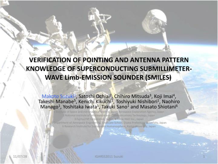
VERIFICATION OF POINTING AND ANTENNA PATTERN KNOWLEDGE OF SUPERCONDUCTING SUBMILLIMETER-WAVE Limb-EMISSION SOUNDER (SMILES).

E N D
VERIFICATION OF POINTING AND ANTENNA PATTERN KNOWLEDGE OF SUPERCONDUCTING SUBMILLIMETER-WAVE Limb-EMISSION SOUNDER (SMILES) Makoto Suzuki1, Satoshi Ochiai2, Chihiro Mitsuda3, Koji Imai4, Takeshi Manabe5, Kenichi Kikuchi1, Toshiyuki Nishibori1, Naohiro Manago1, Yoshitaka Iwata1, Takuki Sano1 and Masato Shiotani6 1 Institute of Space and Astronautical Science, Japan Aerospace Exploration Agency, Japan 2 National Institute of Information and Communications Technology, Japan 3 Fujitsu FIP Corporation, Japan, 4 Tome R&D Inc., Japan 5 Department of Aerospace Engineering, Graduate School, Osaka Prefecture University, Japan 6 Research Institute for Sustainable Humanosphere, Kyoto University, Japan IGARSS2011 Suzuki
JEM/SMILES Mission (JEM/SMILES: Superconducting Submillimeter-Wave Limb-Emission Sounder designed to be aboard the Japanese Experiment Module on ISS; Collaboration project of JAXA - Japan Aerospace Exploration Agency - and NICT - National Institute of Information and Communications Technology -) [Standard Products] • 1 scan: O3, HCl, ClO, CH3CN, O3 isotopes, HOCl, HNO3 • Multi-scan:HO2, BrO [Research Products] UTH, Cirrus Clouds, volcanic SO2, H2O2 1. Demonstration of superconductive mixer and 4-K mechanical cooler for the submillimeter limb-emission sounding in space [Mechanical Cooler] Two-stage Stirling and J-T; 20mW @4K, 200mW @20K, 1000mW @100K; Power Consumption: <300 W; Mass: 90 kg [SIS Mixer] RF: 640 GHz, IF: 11-13 GHz; Junction: Nb/AlOx/Nb, ~7 kA/cm2; Fabricated at Nobeyama RO 2. Observation on atmospheric minor constituents in the middle atmosphere Presentation at Hokkaido U.
JEM/SMILES Payload • Dimension: • 1.85 m x 1 m x 0.8 m • Weight: < 500 kg • Mission Life: 1 year SMILES The SMILES was carried by the H-IIB with the H-II Transfer Vehicle (HTV) (Sep. 11); the HTV was attached to the ISS (Sep. 18); the SMILES was attached to the JEM (Sep. 25) (All dates in JST) Presentation at Hokkaido U.
Two Bands among Band A, B, C can be observed. Band A Band B Band C Frequency region has been selected by engineering interest, as high as possible, but 625-626 GHz region is the only frequency to measure HCl below 1 THz. At 600 GHz troposphere is opaque in limb. Tsys ~ 350 K, and Noise floor is ~0.4 K, given by ACE meeting, M. Suzuki et al
Scientific targets of SMILES 1. Inorganic Chlorine chemistry • ClO to HCl ratio (O3 trend in the US) • HOCl production (O3 trend in the LS) • Global ClO (background ClO) 2. Bromine budget (very short-lived source gas issue) 3. HOx budget etc. Simulated SMILES observation performance Error estimation for the mid-latitude case based on the single scan measurement ACE meeting, M. Suzuki et al
version 1.3 SMILES L2 data It is already comparable to other satellite data, Aura/MLS, SciSAt-1/ACE-FTS, ENVISAT/MIAPS, TIMED/SABER etc. IGARSS2011 Suzuki
ver. 1.3 O3 O 55 deg < latitude < 65 deg Ref – SMILES (Ref – SMILES) / |SMILES| The SMILES L2O3 has a negative bias with respect to ACE-FTS and MLS at around 50 km. However O3 measurements are well determined within 5% differences at 20-40 km.
ver. 1.3 HCl 55 deg < latitude < 65 deg Ref – SMILES (Ref – SMILES) / |SMILES| The SMILES L2 HCl has a negative bias with respect to ACE-FTS and MLS at around 50 km. However it is almost similar to those of the comparison instruments below 45 km.
MLS vs. SMILES: ClO (daytime) O Cl Coincidence events: SMILES (59) for MLS v2.2 (92) SMILES (59) for MLS v3.3 (92) | t | < 24 hour, | r | < 200 km, | sza | < 2 deg -35 deg < latitude < -25 deg The SMILES L2 ClO is in good agreement with MLS v2.2 and v3.3. Ref – SMILES (Ref – SMILES) / |SMILES|
SMILES is expected to provide break-through data, not the yet another satellite data.such as "Global ClO distribution" ? The background ClOx level is important to quantify the in-situ O3 loss at mid-latitudes. However, its global distribution has not been observed with high precision. SMILES provides global ClO distribution with high precision. Furthermore, measurements of ClO, HCl, HOCl, and HO2 can provide important insights into the Cly chemistry. 25 ppt at EQ 22km ? MLS 25 ppt @22km this work Santee et al., 2008 ACE meeting, M. Suzuki et al
SMILES retrieval requires detailed knowledge of instrument function. • y = F(x) + e • Y: measurements, x: physical parameters • F: Forward mode, both atmospheric and instrumental • e: noise • SMILES has significantly lower noise compared to previous instruments, Aura/MLS etc, due to 4 K cooled detector system. It requires detailed and improved forward model for the retrieval, especially on the instrument function. • In the IGARSS 2011, 3 papers on SMILES instrument function have been presented: • S. Ochiai et al, Gain Nonlinearity Calibration of the SMILES reciever. • H. Ozeki et al, RESPONSE CHARACTERISTICS OF RADIO SPECTROMETERS OF THE SUPERCONDUCTING SUBMILLIMETER-WAVE LIMB- EMISSION SOUNDER (JEM/SMILES) • This paper. IGARSS2011 Suzuki
Left: AOS characteristicsRight: Nonlinearity correction Fig2: A spectral image of comb signal Fig4 : Temporal variation of resolution (AU1) IGARSS2011 Suzuki
Pointing Knowledge, Accuracy • Pointing knowledge is critical for limb observation. • SMILES pointing knowledge: • ISS attitude data • SMILES attitude (star sensor) • SMILES antenna angle resolver IGARSS2011 Suzuki
It was found that there might be jitter among attitude data.ISS attitude data should be corrected, using MAXI-ISS jitter data. Fig. 1 Relative difference between MAXI GPS 1pps signal and the ISS clock telemetry data. IGARSS2011 Suzuki
ISS attitude gives much smooth retrieved profile.After the jitter correction, systematic bias also disappeared. Fig. 2 Retrieved O3 profiles using the SMILES Star Sensor data (left) and ISS attitude data (right). IGARSS2011 Suzuki
Tentative conclusion on pointing knowledge • ISS attitude (GPS triangulation) looks to be stable and reliable for SMILES retrieval. • SMILES star sensor (raw data) looks noisy, as expected from its specification. • Temporal mechanical alignment is calculated from the average difference of ISS attitudes and SMILES star sensor data. • There is timing jitter between SMILES (MAXI or JEM) and ISS attitude telemetry. • After the timing jitter correction, SMILES O3 profile became very smooth. • Actual random error of SMILES O3 data looks to be affected by uncertainty of pointing knowledge (random error of pointing mirror angle resolver, which is ~ 60 m in tangent height, or ~ 1% in L2 O3 value). • Detector noise (Tsys ~340 K) should give random error of L2 O3 << 0.5 %. IGARSS2011 Suzuki
Offset Cassegrain, 400 mm (vertical) x 200 mm (horizontal) elliptical shaped antennaScan step 0.009375 deg (33.75’’), resolver +/- 0.0015 deg (5.4’’) IGARSS2011 Suzuki
Fig. 3 Two dimensional (Elevation, Azimuth) SMILES antenna pattern.[7] T. Manabe, et al., “Measurements of the Offset-Cassegrain Antenna of JEM/SMILES Using a Near-Field Phase-Retrieval Method in the 640 GHz Band”, 21st International Symposium Space Terahertz Technology, Oxford UK, March 23-25, 2010. IGARSS2011 Suzuki
Fig. 4 One dimensional antenna pattern in elevation axis without antenna motion (dark), and with antenna motion (light). IGARSS2011 Suzuki
Fig. 5 Averaged retrieved profiles (red: moving antenna, blue: fixed antenna), relative difference normalized to a priori of L2 ver. 1.3 O3 (upper left), temperature (upper right), HCl (lower left) and BrO from SMILES Band A (lower right). 261 observations are averaged in Oct. 12, 2009 at equatorial region N10-S10. Band A O3 IGARSS2011 Suzuki
Fig. 5 Averaged retrieved profiles (red: moving antenna, blue: fixed antenna), relative difference normalized to a priori of L2 ver. 1.3 O3 (upper left), temperature (upper right), HCl (lower left) and BrO from SMILES Band A (lower right). 261 observations are averaged in Oct. 12, 2009 at equatorial region N10-S10. Band A Temp. IGARSS2011 Suzuki
Fig. 5 Averaged retrieved profiles (red: moving antenna, blue: fixed antenna), relative difference normalized to a priori of L2 ver. 1.3 O3 (upper left), temperature (upper right), HCl (lower left) and BrO from SMILES Band A (lower right). 261 observations are averaged in Oct. 12, 2009 at equatorial region N10-S10. Band A HCl Figure in the manuscript was mistake. IGARSS2011 Suzuki
Fig. 5 Averaged retrieved profiles (red: moving antenna, blue: fixed antenna), relative difference normalized to a priori of L2 ver. 1.3 O3 (upper left), temperature (upper right), HCl (lower left) and BrO from SMILES Band A (lower right). 261 observations are averaged in Oct. 12, 2009 at equatorial region N10-S10. Band A BrO IGARSS2011 Suzuki
Conclusion on Antenna Pattern • The difference of antenna pattern affects the weighting function, K, in Eq. (1), and it thus changes retrieved profiles. • Fig. 5 shows an example of systematic difference between moving and fixed antenna pattern. • The systematic differences with considering moving antenna are ~2% for O3 and < 1% for temperature. • Systematic differences for other species are from ~2% for HCl (strong spectral signal) to ~30% for CH3CN (very weak spectral signal overlapped by other species). • It is concluded that the moving antenna pattern should be used for the L2 retrieval. Systematic errors due to the moving antenna should be negligibly small (multiply ~2% for O3 by -55 dB for antenna pattern uncertainty). IGARSS2011 Suzuki
Summary • Pointing knowledge of the SMILES for the L2 retrieval system can be calculated properly from the ISS attitude with corrections (ISS telemetry timing jitter, and structural difference). • The one-dimensional model of antenna pattern based on the physical-optics calculations and the phase-retrieval measurements od the antenna flight model was implemented in the SMILES operational L2 retrieval system. • Systematic errors of L2 products are estimated to be ~1% for the pointing and negligibly small for the antenna pattern treatment. • The results from 3 papers in IGARSS 2011 are implemented in the next L2 version (ver 2.0, under test run). IGARSS2011 Suzuki


![NATIONAL RURAL LIVELIHOODS MISSION [NRLM]](https://cdn0.slideserve.com/652488/slide1-dt.jpg)