Download
1 / 3
30 likes | 108 Views
Geometric constraint. Upper limit, 348mm. Cavity, 139mm. Beam axis, 0mm. Current design. 143mm. 3mm Nb , 5mm cooling channel and 2mm vessel. Upper limit, 348mm. 40mm. 338mm. 33mm for flange. Cu gasket , 255mm. Cavity, 139mm. Beam axis, 0mm. Properties.

E N D
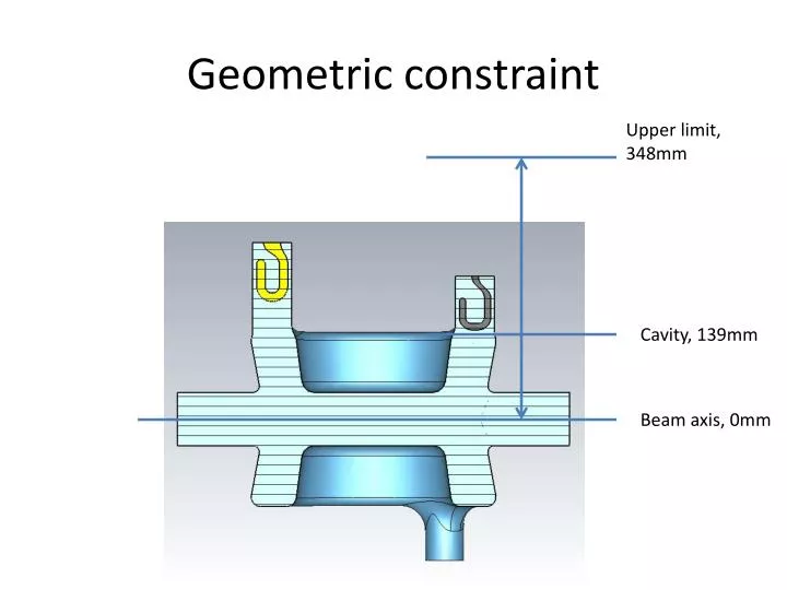
Geometric constraint Upper limit, 348mm Cavity, 139mm Beam axis, 0mm
Current design 143mm 3mm Nb, 5mm cooling channel and 2mm vessel Upper limit, 348mm 40mm 338mm 33mm for flange Cu gasket, 255mm Cavity, 139mm Beam axis, 0mm
Properties • HOM ports at 255mm away from beam axis • 5mm cooling channel • Loss on each gasket: 11.3mW (Considering 1.3 coefficient from surface roughness -> 14.7mW) • Coupling to 400MHz: 7.9x10⁹ (0.15W each port) • Peak magnetic field on the cavity: 71.6mT • Peak magnetic field on the hook: 93% of that on the cavity, further study needed • Impedance calculation is on-going, Ben is working on the R/Q calculation.