Download
1 / 35
420 likes | 515 Views
ELECTRICAL MACHINES. An electrical machine is an electro-mechanical energy conversion device. The device which converts electrical energy to mechanical energy is called a motor. The device which converts mechanical energy to electrical energy is called a generator. Electrical energy.

E N D
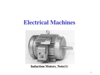
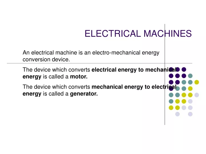
ELECTRICAL MACHINES An electrical machine is an electro-mechanical energy conversion device. The device which converts electrical energy to mechanical energy is called a motor. The device which converts mechanical energy to electrical energy is called a generator.
Electrical energy Mechanical energy Out put input MOTOR
GENERATOR Electrical energy Mechanical energy Out put input
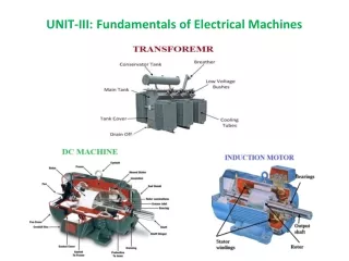
CLASSIFICATION OF ELECTRICAL MACHINES ELECTRICAL MACHINES Direct current machines Alternating current machines DC generator DC motor Transformers Induction Synchronous Fractional KW machines MachinesMachines
DC GENERATOR • Principle of operation: • DC generator works on the principle of Faradays laws of electromagnetic induction.It states that • “Whenever magnetic flux is cut by a moving conductor ,an emf is induced in the conductor”. • Direction of induced emf is given by Flemings Right Hand rule. • Stretch out right hand thumb ,fore finger,middle finger mutually perpendicular to each other.If the fore finger points in the direction of flux and thumb in direction of motion of conductor,then the middle finger will point in the direction of induced emf.
Principle of working • Consider a single turn rectangular coil made of copper rotating about its own axis in a magnetic field provided by either permanent magnet or electro magnet. Consider a copper coil ABCD ,rotating in a magnetic field as shown in slide. • The two ends of the coil are joined to two copper rings called slip rings .Brushes of carbon ,press against slip rings for collecting current from the coil to external load resistance RL. • Consider position of the coil(as shown in fig) as reference .In this position plane of the coil is right angles to the magnetic lines of flux.In this position rate of change of flux lis minimum and no emf induced in the coil. The position is taken as the reference position.Measure the angle of rotation or time from this position. As the coil rotates, the rate of change of flux and hence the induced emf increases ,till atᶱ= 90 ,when the coil plane is horizontal ,the induce emf is maximum.
In the next quarter ,from ᶱ= 180 to 360 ,the variation of emf are similar to first half.It is minimum when plane of coil is perpendicular to lines of flux and maximum when plane of coil is parallel to the lines of flux. however in both cases coil sides cuts the lines of flux in opposite directions. Therefore emf in the coil is reversed. • Induced emf e= BlVsin ᶱ • where e= induced emf in volts • B= magnetic field intensity • l = length of the conductor • V= relative velocity b/w field and conductor in m/s • ᶱ = angle between plane of rotation and plane of flux.
SIMPLE LOOP GENERATOR Elementary Generator
3 Simple d.c. generator similar to a.c. generator different from a.c. generator commutator Every time the coil passes through the vertical, it reverses coil's connections with outside circuit. Iin the outside circuit always flows in 1 direction.
Parts of a practical generator • Magnetic frame or yoke • Pole-cores and Pole shoes • Pole coils or field coils • Armature core • Armature windings or conductors • Commutator • Brushes and bearings
pole A four pole DC generator yoke
Yoke or outer frame • Outermost cylindrical part of the machine. • FUNCTIONS: • Acts as the supporting frame for the machine. . Carry the magnetic flux produced by the poles. • To provide mechanical support to the poles. • Made of cast iron(small machines) or cast steel(large m/c)
Poles • Pole consists of pole core and pole shoe. • Field coil is wound on pole core. • Poles are made of cast steel and forged steel. • Pole is securely bolted to the yoke. • FUNCTIONS: • Pole core carries a field winding which is necessary to produce magnetic flux. • It directs the flux through the armature core.
Pole shoe Naturally pole shoe is a projection over pole core and is always with connection with pole body and fills the gap between the yoke and the pole body. • Functions of pole shoes It supports the field coil. It spreads out the magnetic flux in the air gap. It reduces the reluctance of the magnetic path. A combination of pole body and pole shoe is termed as field magnet. This behaves as a field magnet when direct current is passed through the field coil.
Field or Pole coils • The fields coils are wound on pole cores. • The field or pole coils ,made from enameled copper wire or strip. • FUNCTION: • Function of this coil is to produce the necessary flux ,when current is passed through it. Since it produces the flux its also called exciting winding. The field coils are so connected that they form alternate N and S poles.
Armature • Part of DC machine where an emf is induced as it rotates relative to the main field. • Consists of toothed core ,a winding and a commutator mounted on armature shaft.
Armature Core • Armature core is cylindrical in shape and is mounted on the shaft. It consists of slots on its periphery to house the conductors. • Made of cast iron or cast steel. FUNCTIONS: • To house the armature conductors. • To provide a path of low reluctance to the field from the N-pole to S-pole ,through the armature.
Armature windings • A number of conductors ,housed on the armature core ,are interconnected in a manner to add up the induced emf produced in the conductors. The interconnected conductors constitute armature winding FUNCTIONS: • generation of emf. • Carry the armature current supplied to the load in case of generators and carry the current supplied in case of dc motors. • 2 types of winding are there: lap and wave.
Lap winding • In this connection ,the winding overlap. • The conductors are connected in series parallel combination to increase the voltage and current rating. Series connection increase vtg rating and parallel increases the current rating. • Armature coils are connected in series through commutator segments in such a way that armature winding is divided into as many paths as the number of poles of the machine .
Cont.. • In lap winding the total number of parallel paths = no of poles’p’. Hence lap winding is preferred for machines with high current rating.
Wave winding • In this connection ,thw winding does not overlap. • Armature coils are connected in series through commutator segments in such a way that the armature winding is divided into two parallel paths irrespective of the number poles of the machine.This type of winding is preferred for low current high voltage generators.
Lap winding Wave winding 1) Number of parallel paths A= 1) A=2 No of poles ,P 2 ) No of brushes = p 2) no of brushes = 2 3) Preferred for high current –low 3) preferred for low current highvtg Voltage generators. Generators. 4) Used when current is grater than 4) used when current is less 500 A than 500 A
Commutator • Commutator is a most important and vital part in a D.C generator without which the generator fails to work.Rectification of current is the main function of the Commutator. It converts the alternating current induced in the armature winding in to directional current. • It is of cylindrical structure and made of wedge-shaped segments made of high-conductivity copper. These segments are insulated from one another by thin layers of mica.Each segment is connected to the armature conductor by means of a copper strip or plug.
Brushes and bearings • Brushes are stationary and rest on the surface of the commutator. • they are made of carbon. • They are housed in a box type brush holders which are open at both the ends. FUNCTION: • To collect current from commutator and make it available to the external circuit. BEARINGS: • Ball bearings are used commonly because of their reliability. Roller bearings are used for heavier duties.
Shaft shaft is the central one over which the whole parts are loaded. .
DIFFERENT TYPES OF DC GENERATORS Separately excited Self excited Series wound shunt wound compound wound Long shunt short shunt
Dc generators are generally classified according to the method used for field excitation. • They are • 1) separately excited generator • 2)self excited generator
Separately excited generator • In these the field magnets are energized from a separate independent external source of dc current. • A separate dc source is used to drive the field current If. The resistance Rf is connected to adjust the field current. • the emf generated in the armature drives the load. Armature current and Ioad current is same.