Download
1 / 19
200 likes | 208 Views
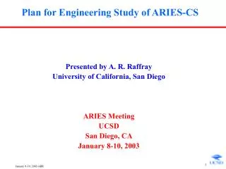
Key Physics & Technology Issues for Compact Stellarator Power Plants. Farrokh Najmabadi UC San Diego 18 th International Toki Conference December 9-12, 2008 Toki, Japan. Key R&D Issues – Observations from the ARIES-CS study.

E N D
Key Physics & Technology Issues for Compact Stellarator Power Plants Farrokh Najmabadi UC San Diego 18th International Toki Conference December 9-12, 2008 Toki, Japan
Key R&D Issues – Observations from the ARIES-CS study • ARIES-CS study was completed in 2007. Final report is published in J. Fusion Science & Technology 2008. • ARIES CS was the first integrated design of a compact stellarator; designs was pushed in many areas to uncover difficulties. • Many issues were identified. <R> = 7.75 m, <Bo> = 5.7 T, FPC Mass = 11,000 tonnes (size & mass comparable to advanced tokamaks)
Goals of the ARIES-CS Study • Can compact stellarator power plants be similar in size to advanced tokamak power plants? • Physics: Reduce coil aspect ratio, Ac = <R>/Dmin while maintaining “good” stellarator properties (focused on QA configuration) • Engineering: Reduce the required minimum coil-plasma distance. • What is the impact of complex shape and geometry? • Complex 3-D analysis (e.g., CAD/MCNP interface for 3-D neutronics) • Complexity-driven constraints (e.g., superconducting magnets) • Configuration, assembly, and maintenance • Manufacturability (feasibility and Cost)
N3ARE N3ARE LI383 Frequency *4096 Energy (keV) Energy (keV) Optimization of NCSX-Like Configuration: Improving a Confinement • A bias was introduced in the magnetic spectrum in favor of B(0,1) and B(1,1): • A substantial reduction in a energy loss (from ~18% to ~ 4-5%) is achieved. • a loss may be too high (localized heating and exfoliation concerns) Baseline Configuration
N3ARE Optimization of NCSX-Like Configuration: Increasing Plasma-Coil Separation • A series of coil design with Ac=<R>/Dmin ranging 6.8 to 5.7 produced. • Large increases in Bmax /Bo only for Ac < 6. Ac=5.9 For <R> = 7.75m: Dmin(c-p)=1.32 m Dmin(c-c)=0.8 m
Many attractive QA configurations exists! Example: MHH2 • Low plasma aspect ratio (Ap ~ 2.5) in 2 field period. • Excellent QA, low effective ripple (<0.8%), low a energy loss ( 5%) . • Less complex coils with a relatively large coil to coil spacing
Stellarator Configuration Space is rich with interesting configurations • Typical configuration optimization process includes criteria on transport, equilibrium, stability, etc. Each criterion is assigned a threshold and a weight in the optimization process. In-depth understanding of relative importance of these criteria on overall performance system is needed. • Understanding of b limits in stellarators is critical. • Configurations with reduced α-particle loss should be developed. • Demonstration of profile control in compact stellarators (e.g., QA) to ensure the achievement and control of the desired iota profile, including bootstrap current effects.
Goals of the ARIES-CS Study • Can compact stellarator power plants be similar in size to advanced tokamak power plants? • Physics: Reduce coil aspect ratio, Ac = <R>/Dmin while maintaining “good” stellarator properties (focused on QA configuration) • Engineering: Reduce the required minimum coil-plasma distance. • What is the impact of complex shape and geometry? • Complex 3-D analysis (e.g., CAD/MCNP interface for 3-D neutronics) • Complexity-driven constraints (e.g., superconducting magnets) • Configuration, assembly, and maintenance • Manufacturability (feasibility and Cost)
Replaceable FW/Blkt/BW | Thickness (cm) | 63 28 32 35 2.2 28 19.4 >2 ≥2 5 Full Blanket& Shield FS Shield (permanent) SOL 25 cm Breeding Zone-I 25 cm Breeding Zone-II 3.8 cm FW Plasma Vacuum Vessel Coil Case & Insulator Gap 5 cm Back Wall 1.5 cm FS/He He & LiPb Manifolds Winding Pack Gap + Th. Insulator Strong Back 1.5 cm FS/He 0.5 cm SiC Insert | | ≥179 cm Thickness (cm) 28 2.2 19.4 2 28 3.8 5 2 34 25 14 5 Non- uniform Blanket & Shield @ min FS Shield-I (replaceable) WC Shield (permanent) Gap + Th. Insulator Blanket FW Winding Pack Coil Case & Insulator SOL Back Wall Strong Back Gap Plasma Vacuum Vessel min = 131 cm | | Minimum Coil-plasma Stand-off Can Be Reduced By Using Tapered-Blanket Zones
Major radius can be increased to ease engineering difficulties with a small cost penalty
Goals of the ARIES-CS Study • Can compact stellarator power plants be similar in size to advanced tokamak power plants? • Physics: Reduce coil aspect ratio, Ac = <R>/Dmin while maintaining “good” stellarator properties (focused on QA configuration) • Engineering: Reduce the required minimum coil-plasma distance. • What is the impact of complex shape and geometry? • Complex 3-D analysis (e.g., CAD/MCNP interface for 3-D neutronics) • Complexity-driven constraints (e.g., superconducting magnets) • Configuration, assembly, and maintenance • Manufacturability (feasibility and Cost)
Toroidal Angle IB Poloidal Angle IB First ever 3-D modeling of complex stellarator geometry for nuclear assessment using CAD/MCNP coupling • Detailed and complex 3-D analysis is required for the design • Example: Complex plasma shape leads to a large non-uniformity in the loads (e.g., peak to average neutron wall load of 2). Distribution of Neutron wall load
Coil Complexity Impacts the Choice of Superconducting Material • Strains required during winding process is too large. • NbTi-like (at 4K) B < ~7-8 T • NbTi-like (at 2K) B < 9 T, Potential problem with temperature margin • Nb3Sn B < 16 T, Conventional technique does not work because of inorganic insulators • Option 1: Inorganic insulation, assembled with magnet prior to winding and capable to withstand the heat treatment process. Option 2: conductor with thin cross section to get low strain during winding. (Low conductor current, internal dump). Option 3: HTS (YBCO), Superconductor directly deposited on structure.
Coil dimensions Coil dimensions Cover plate 2 cm thick 19.4 cm x 74.3 cm Filled with cables Filled with cables Inter Inter - - coil Structure coil Structure Strongback Strongback Nominally 20 cm 28 cm 28 cm Coil Complexity Dictates Choice of Magnet Support Structure • It appears that a continuous structure is best option for supporting magnetic forces. • Net force balance between field periods (Can be in three pieces) • Superconductor coils wound into grooves inside the structure.
Components are replaced Through Ports • Modules removed through three ports using an articulated boom. Drawbacks: • Coolant manifolds increase plasma-coil distance. • Very complex manifolds and joints • Large number of connect/disconnects
Manufacturing of blanket modules is challenging • Dual coolant with a self-cooled PbLi zone and He-cooled RAFS structure and SiC insert: • The complex internal components should be manufactured with the desired 3-D shape. • Impact of Ferritic material on the stellarator configuration is unknown.
W armor W alloy inner cartridge W alloy outer tube A highly radiative plasma is needed for divertor operation • Heat/particle flux on divertor was found by following field lines outside LCMS. • Because of 3-D nature of magnetic topology, location & shaping of divertor plates require considerable iterative analysis. Top and bottom plate location with toroidal coverage from -25° to 25°. • T-Tubes divertor module is based on W Cap design (FZK) extended to mid-size (~ 10 cm) with a capability of 10 MW/m2
In Summary: • Understanding of b limits in stellarators is critical. • Configurations with negligible α-particle loss should be developed. • Configuration, assembly, and maintenance drives the design • Component replacement through ports appears to be the only viable method. This leads to many non-identical modules, large coolant manifolds (increased radial build), large number of connects and disconnects, complicated component design for assembly disassembly. • 3-D analysis of components is required for almost all cases, New tools may have to be developed for component optimization. • Feasibility of manufacturing of component should be included in the configuration design as much as possible. For ARIES-CS, manufacturing of many components is challenging and/or very expensive. • Stellarator configuration optimization should include “strong” penalties for complex plasma (and coil) shape.