Download

1 / 13
160 likes | 321 Views
Self Calibrating Light Source. Self Calibration of Probe Card Light Source Sponsored By :. What is a Probe Card?. A Probe card is the interface between the Die to be tested and the Test equipment.

E N D
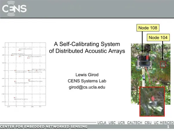
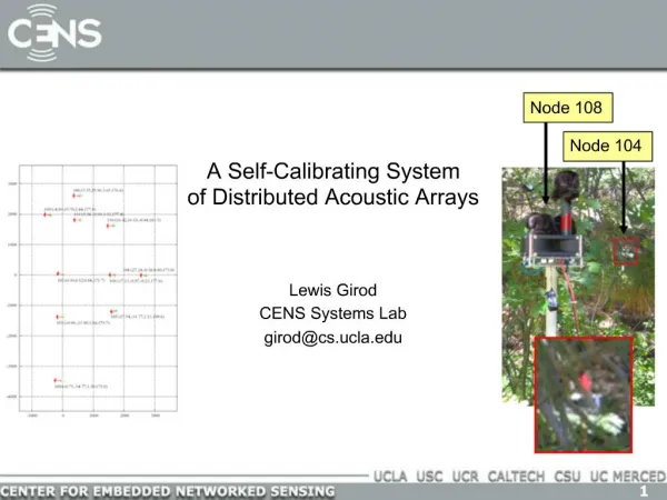
Self Calibrating Light Source Self Calibration of Probe Card Light Source Sponsored By :
What is a Probe Card? • A Probe card is the interface between the Die to be tested and the Test equipment. • The probe card is positioned over each die and with small probes touches the bond pads to turn the part on and test device
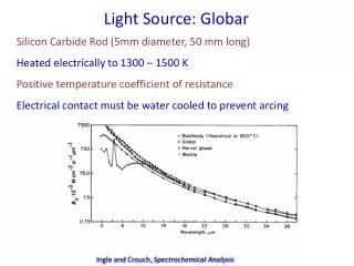
Overview • On Semiconductor has several devices that are light sensing devices. • These Devise measure Ambient and IR light • The primary market for these devices are cellphones but there are other applications. • The tester for these products does not have a light source to stimulate the parts during testing. • A PC board with some LEDs is added to the Probe card to give us a light source.
Current Probe Card Light Source LED PCB Top Headers for interface to Generic J750 Probe Card LED PCB Bottom 2 Ambient LEDs (Osram Obsolete) 1 IR LED (Osram Obsolete)
Light Measurement • We have to know how much light is being exposed to the devices in order to test them to the limits • We have to measure inferred light and ambient light • In order to give us this capability we add a second board to the probe card with calibrated sensors.
Light Measurement Headers for interface to Generic J750 Probe Card Ambient Light Sensor Inferred Light Sensor • Ambient Light (400nm – 700nm) • Inferred Light (850nm) • Both of the Sensors are ON semi proto type parts that are now obsolete and need to be replaced
CalibrationSystem Using 2 Sensors board, (one on top and one on bottom of the probe card),the Light source is manually tested and calibrated on a Test bench before it is used on the test floor. This process is done manually is time consuming and tedious Results are good but inconsistent from Board to board
Problems: • Inconsistent Light from the LED light source • Inconsistent light from probe card to probe cade • Inconsistent light from site to site, 12 sits tested at a time • No on site calibration for the light source • Only Manual calibration of the light source is currently available • Must be calibrated on a test bench away from the tester. • This waists tester time and engineering resources.
Illustration of the Problem: Approximate Ambient Light Pattern Ambient LEDs LED PC board Approximate Inferred Light Pattern Wafer Die 12 sites Inferred LEDs
Solution: • The solution to the problem is to build a new probe card with a better measurement system and better light source management • We have to solve three problems • We have to build a better Light source • We have to provide a better measurement system • Both the Light Source and the measurement system have to be compatible with a calibration algorithm
Project Proposal • The proposal is a three part process. • build a light source that will provide a better average of light over a wider area • Build a better system for measuring the light. • We will need more measurement location • Verify all individual LEDs are working. • Use off the shelf parts for easier long term maintenance. • High consistency from part to part • Create an algorithm that will adjust the light level automatically and compensate for LED difference from part to part and degradation overtime
Participants • There is a need for two to three participants on this project • Hardware Designer • Probe Card and LED PC board layout • Tester interface and resource management • Lighting and Measurement Designer • Light distribution for IR and Ambient Sources • Light distribution model using Matlab • Measurement scheme and hardware • Algorithm Development • Develop a process of measuring the light and adjusting the light source but can not change the response of the LEDs • Test each individual LED to verify functionality
Project Opportunity With a Potential Employer Thanks for your time Samuel Anderson