Download
1 / 1
10 likes | 118 Views
LINK BUDGET ANALYSIS OF FREE-SPACE OPTICAL (FSO) COMMUNICATION NETWORKS Serhat Aslandoğdu- Özer Yıldız Electronic and Communication Engineering Department, Cankaya University. Abstract

E N D
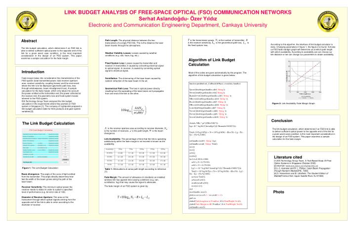
LINK BUDGET ANALYSIS OF FREE-SPACE OPTICAL (FSO) COMMUNICATION NETWORKS Serhat Aslandoğdu- Özer Yıldız Electronic and Communication Engineering Department, Cankaya University Abstract The link budget calculation, which determines if an FSO link is able to deliver sufficient optical power to the opposite end of the link for a given worst case condition, is the most important consideration in the design of an FSO system. This paper examines a sample calculation for the fade margin. Path Length: The physical distance between the two transceivers of a single FSO link. This is the distance the laser beam travels through the atmosphere. Weather Visibility Losses: Losses caused by weather conditions (e.g. rain, haze, fog, etc.). Fixed System Loss: Losses caused by transmitter and receiver. In transmitter, it caused by converting electrical signal to optical signal. In receiver, it caused by converting optical signal to electrical signal. Scintillation: The shimmering of the laser beam caused by random refraction of the laser beam in the air. Geometrical Path Loss: The loss in optical power directly resulting from the spreading of the laser beam as it propagates from one end of the link to the other. is the transmission power, is the number of transmitter, is the receiver sensitivity, is the geometrical path loss, is the fixed system loss. According to this algorihm, the interface of link budget calculator is done. Changing parameters in figure 1, the figure 2 is found. It shows us FSO fade mardgin graph will determine us at which path length with which availability. According to availability we can choose our link distance or we can change our parameters to obtain availability. Algorithm of Link Budget Calculation Most of the codes are gave automatically by the program. The algorithm of link budget calculation is given below: Introduction Fade margin takes into consideration the characteristics of the FSO system (total transmitted power, total receiver aperture area, receiver sensitivity, coupling losses) and the enviroment where the link is to be deployed (geometric path loss, loss through windowpanes, beam misalignment loss). A sample calculation for the fade margin, which only takes into account the power emitted at the transmitter end, the power collected at the reciever end, the geometric loss and fixed system losses inherent to the FSO system. IDA Technology Group Team analyzed the link budget calculation in the experiments where they worked on FSO system in Singapore [1]. The company of Lightpointe prepared a link budget calculation table for their products and gave system variables [2]. Figure 2: Link Availability Fade Margin Graph The Link Budget Calculation Conclusion is the receiver aperture area according to receiver diameter, is the number of receivers, is the path length, is the beam divergence. Link Availability: The percentage of time that the link is operating satisfactorily when the fade margin is not exceed is known as link availability. The link budget calculation, which determines if an FSO link is able to deliver sufficient optical power to the opposite end of the link for a given worst case condition, is the most important consideration in the design of an FSO system. This paper examines a sample calculation for the fade margin. Literature cited [1] IDA Technology Group Team, A Trial-Based Study Of Free Optics Systems in Singapore (October 2002) [2] internet// www.tera-wave.com/lightpointe.xsl [3] L.C. Andrews and R. L. Philips, Laser Beam Propagation through Random Media(SPIE, 1998) [4] D. Hanselman and B. Littlefield, The Student Edition of Matlab(Prentice Hall, Upper Saddle River, NJ 07458) Figure 1: The Link Budget Calculation Table 1: Attenuations at varius path length according to reference [1] Beam divergence: The angle of the cone of light emitted from the transmitter. This angle directly determines how fast the width of the beam grows along the path of the laser beam. Fade Margin: The amount of allowance (in decibels) an installed wireless link has against time-varying conditions (e.g. rain, scintillation, fog) that may cause the signal to attenuate. The fade margin of an FSO system is given by: Receiver Sensitivity: The minimum optical power the receiver needs to detect in order to sustain a specified level of performance (e.g. bir-error rate of 108). Diameter of Receiver Aperture: The area on the transceiver through which optical signals arriving from the opposite end of the link is able to enter according to the diameter of receiver. Photo