Download
1 / 20
200 likes | 330 Views
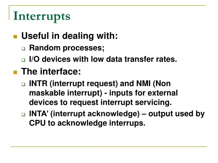
Interrupts. Useful in dealing with: Random processes; I/O devices with low data transfer rates. The interface: INTR (interrupt request) and NMI (Non maskable interrupt) - inputs for external devices to request interrupt servicing.

E N D
Interrupts • Useful in dealing with: • Random processes; • I/O devices with low data transfer rates. • The interface: • INTR (interrupt request) and NMI (Non maskable interrupt) - inputs for external devices to request interrupt servicing. • INTA’ (interrupt acknowledge) – output used by CPU to acknowledge interrups.
Interrupt Vector Table • Table located at addresses 000000H – 0003FFH, the first 1024 bytes of memory.
BOUND, INTO, INT, INT3 and IRET • BOUND and INTO are conditional interrupts. • BOUND AX,DATA • IF AX is less than DATA+1:DATA then an INT 5 occurs. • IF AX is greater than DATA+3:DATA+2 then an INT 5 occurs. • IF AX is within bounds of the two words in memory (DATA+1:DATA ≤ AX ≤ DATA+3:DATA+2) then an INT 5 does not occur. • INTO • If OF=1 then INT 4 occurs. • If OF=0 then INTO performs a NOP operation and the next instruction in the program is executed.
BOUND, INTO, INT, INT3 and IRET • INT type • INT 3 – Breakpoint interrupt • IRET • These instructions modify the EIP register to be the address stored at: • The IDT. The interrupt type or number is used to identify which element of the IDT holds the addresses of the desired interrupt service subroutines; • The stack. The address stored in the stack by the INT or INTO instruction. This address identifies the return point after the interrupts execution.
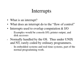
Sequence of Events • When the microprocessor finishes executing an instruction it determines if an interrupt is active by checking: • Instruction execution; • Single-step; • NMI; • Coprocessor segment overrun; • INTR; • INT.
Sequence of Events • If any of the previous conditions are presents, the following will happen: • The contents of the flag registers are pushed onto the stack; • Both IF and TF are cleared. This disables the interrupt pin and the trap (single step feature); • CS:IP are pushed onto the stack; • The interrupt vector are fetched and they will replace the values in CS:IP. • Interrupt subroutine is executed.
Sequence of Events • IRET: • Pops the return addresses out the stack and uses them to modify the contents of the IP. • Return the IF and TF flags to their original states which were stored in the stack.
Hardware Interrupt • Notice the sequence of events described in the timing diagram: • Interrupt request is asserted; • Interrupt acknowledge is asserted twice; • Vector is placed on the data bus on the second pulse of the interrupt acknowledge signal.
Simple Hardware Interrupt Circuit • This circuit places vector number 80H on the data bus when the interrupt acknowledge signal is asserted.
8255 Circuit With Interrupt • The 8255 generates the interrupt through port C after it receives the request from the keyboard. • The 74LS244 places the interrupt vector on the data bus when the interrupt acknowledge is received.
8259A PIC • The 8259A programmable interrupt controller: • Adds vectored priority encoded interrupts to the microcontroller; • Can handle up to 64 interrupt requests. This requires the use of a master and eight slaves; • Built by Intel and other manufacturers.
8259A PIC • D0 – D7: Data lines; • A0: Address line; • IR0 – IR7: Interrupt request inputs; • WR’: Write input; • RD’: Read input; • INT: Interrupt output; • INTA’: Interrupt acknowledge input; • CS’: Chip select input; • SP/EN’: Slave program/enable buffer; • CAS0 – CAS2: Cascade lines.
Programming the 8259A • The 8259A is programmed by properly initializing: • 4 ICWs - Initialization command words; • 3 OCWs – Operation command words; • The initialization procedure may not need to initialize all of them.
Programming the 8259A • Use the flow chart shown to the left to guide you in which order and how many ICWs you may need to initialize. • ICWs must be initialized before the OCWs.