Download
1 / 19
190 likes | 459 Views
MAPLD 2004 Washington D.C. 8 th – 10 th September 2004 Application and Experience of CAN as a low cost OBDH bus system Adrian Woodroffe Engineer Surrey Satellite Technology Limited, Guildford, UK. Contents. Introduction to Surrey Satellite Technology Ltd. (SSTL)

E N D
MAPLD 2004 Washington D.C. 8th – 10th September 2004 Application and Experience of CAN as a low cost OBDH bus system Adrian Woodroffe Engineer Surrey Satellite Technology Limited, Guildford, UK
Contents • Introduction to Surrey Satellite Technology Ltd. (SSTL) • SSTL Missions using CAN • SSTL CAN bus topology • SSTL CAN hardware solutions • COTS CAN • RadCAN • SSTL CAN for Spacecraft Usage (CAN-SU) protocol • Future development • Conclusion
Surrey Satellite Technology Ltd • Predominantly Low Earth Orbit (LEO) missions • Extensive use of Commercial Off The Shelf (COTS) technology, plus • Module level redundancy • Passive fail safe system design • Provides a low cost solution • Rapid utilisation of new technology • Now moving to small GEO platforms • British National Space Centre funded GEMINI small GEO communications platform • Deployable panels • Harsher radiation environment compared with LEO • Higher reliability requirements
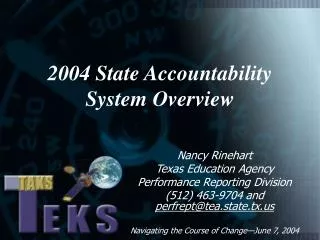
SSTL CAN Flight History No CAN Bus Partial CAN Bus CAN Bus for all TTC
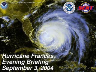
PRIMARY CAN BUS SECONDARY CAN BUS DRIVER DRIVER DRIVER DRIVER DRIVER DRIVER °C CAN μC °C CAN μC °C CAN μC CAN PERIPHERAL °C CAN μC CAN PERIPHERAL TC TLM TC TLM TC TLM μPROC/DSP TC TLM μPROC/DSP SEMI-SMART MODULE SEMI-SMART MODULE TYPICAL DATA PROCESSING MODULE (OBC/SSDR) TYPICAL DATA PROCESSING MODULE (OBC/SSDR) CAN Bus System Topology • Two sub-system categories are connected to the CAN bus • Semi-smart modules that respond to tele-commands and provide telemetry • For example a reaction wheel will have a tele-command to set it speed, and a telemetry value to read it’s speed. The microcontroller will provide the control loop to maintain the set speed. • Data processing modules, onboard computers etc that control the satellite • Generally based round a microprocessor, the OBC will control the attitude and payload functions etc by issuing a set of tele-commands on the CAN bus • Redundant busses are selected via latching relay • A module can be commanded to change to the secondary bus, or • Will automatically switch buses if the module does not receive any messages for 5 minuets
The Environment • Low Earth Orbit • 500Km to 1000Km • Relatively benign radiation environment • <1Krad TID per year at the component (>2mm Alu shielding from module boxes & structure) • SEU rate of approximately 1 per MByte of SRAM per day • SEL, only 4 confirmed cases in SSTL’s flight history • A COTS solution is therefore acceptable if; • The system design is passively fail safe for attitude, power generation and thermal control • Module level cold redundancy • Higher Earth Orbits • MEO and GEO orbits • >10Krad TID per year depending on orbits • More complex systems require guaranteed active attitude control for deployable panels etc • A radiation tolerant (for both TID and SEU / SELs) must be used
DRIVER DRIVER °C CAN μC CAN PERIPHERAL μPROC/DSP TC TLM TYPICAL DATA PROCESSING MODULE (OBC/SSDR) COTS Solution • Semi-Smart Modules • Based round a 8051 microcontroller • On Chip CAN controller • Makes maximum use of microcontroller peripherals • 8 channel, 10 bit ADC for telemetry gathering • PWMs and URATS • Physical CAN transceiver • Latching relay to select bus • Data Processing Units • Microprocessor base • CAN controller memory mapped • Physical CAN transceiver • Latching relay to select bus
COTS Components Flown * assuming 50% are in cold redundant modules & thus off
Radiation Hard Solution • No Radiation Hard 8051 microcontroller with on chip CAN is currently available • The COTS 8051 does not meet radiation for orbits higher then LEO • Aurelia CAST A (8051 with the CASA2 CAN peripheral on the same die is presently under development (see www.caen.it/micro) • Solution for Semi-Smart Modules • Separate 8051 CPU, with an external CASA2 CAN controller (Aurelia design), external PROM, SRAM and ADC had to be provided • Shown as a block diagram on the following slide • Solution for Data Processing Modules • The Existing architecture can be copied using available radiation hard components • Processor: Atmel SPARC 695 • CAN Peripheral: Aurelia CASA2 (Based on ESA HurriCAN IP Core) • CAN Physical • No Radiation Hard device is currently Available • The COTS Phillips device is manufactured Silicon on Insulator and has shown promising total dose performance • Aurelia have EM samples of a Radiation Hard Device • RS485 drives can be interface to the CAN bus with some additional pull-up / pull-down resistors. This option is currently under evaluation
COTS / Radiation Hard comparison COTS Radiation Hard
Protocol Introduction • Higher layer protocol for CAN developed by SSTL: CAN for Spacecraft Usage (CAN-SU) • Used for telemetry, tele-commands and data transfers • Developed in 1995 before the extended 29 identifier was available • Driven by Requirements: • Wide range of required telemetry values from many modules • Support multiple system configurations • Keep it simple • Limitations • 11 bit CAN ID field dictates the need for extended addressing in the CAN data field
CAN-SU Protocol A sequence number used in burst of 8 packets Not discussed further here Address of module or task Sending the message i.e. the OBC Various control bits as defined in the CAN protocol Including data field Length Defines message type; Tele-command, telemetry request etc Address of module or task the message is being sent to i.e. reaction wheel CAN-SU Bit definitions 4 Bytes of Data Telemetry or Telecommand Address ID (8 bits) Seq (3 bits) From ID (8 bits) Control (8 bit) Address (10bits) Data (32bits) CAN Bit definitions 11 Bit CAN Identifier CAN Control 8 bytes of data in each CAN message
Protocol Telecommand Request Source Request Sink Tele-command request Tele-command request ID (8 Bits) Seq = 0 Len = 7 From (8 Bits) Control TC-Req Address (10 Bits) Data 32 Bits Tele-command acknowledge ID (8 Bits) Seq = 0 Len = 7 From (8 Bits) Control TC-Ack Address (10 Bits) Data Response 32 Bits Tele-command ack
Protocol Telemetry Data Sink Data Source Telemetry request Telemetry request ID (8 Bits) Seq = 0 Len = 3 From (8 Bits) Control TL-Req Address (10 Bits) Telemetry response ID (8 Bits) Seq = 0 Len = 7 From (8 Bits) Control TL-Res Address (10 Bits) Data Response 32 Bits Telemetry response
Future Developments (1) • COTS • Microchip PIC 3.3V microcontroller with on chip CAN running at 3.5 MIPS (compared with 1 MIP 8051). • Lower power • FLASH based program code for in-circuit programming (last resort in orbit) • RAD Hard • Evaluate Aurelia CASTA • RadCAN next generation will be a System on a Chip (SoC) solution. • Currently targeted at an Actel RTAX1000 • Combines an open source 8051 IP core with the ESA licensed HurriCAN core, uses FPGA SRAM with EDAC and hard code the 8051 program code, to produce a single chip solution (minus the ADC)
Future Development (2) • RadCAN – Next Generation
Future Developments (3) • Protocol • The use of the 11 bit identifier is severely limiting to CAN-SU • SSTL is investigating a re-work of the CAN-SU protocol to use the 29 bit identifier • The 29 bit identifier could incorporate both CAN task ID and telemetry / tele-command channel number • 29 bit identifier could also mean use of the Remote Frame is possible • CANOpen • SSTL is also investigation the option to migrate to the industry standard CANOpen • http://www.can-cia.de/canopen/ • Heavier protocol than CAN-SU but selected parts could be used to replace and improve on CAN-SU • Provides more complex synchronisation factions if required
Conclusions • COTS components • 10’s of orbit years use on SSTL satellites in LEO • Suitable for radiation benign LEO missions • Sub-system redundancy and fault tolerant system design has resulted in no observed failures of the CAN bus or it’s constituent components. • Radiation Hard CAN solutions • Not many components are available at the present time but this is changing • Hurricane (ESA IP core) • Aurelia CASA 2 (CAN peripheral) • Aurelia CAST A (8051 micro + CAN peripheral), in development • Aurelia CAN Physical driver, in development


![The CENVAT Credit Rules, 2004. [ Notification no. 23/2004-C.E. (NT) dated 10.09.2004]](https://cdn3.slideserve.com/5711726/the-cenvat-credit-rules-2004-notification-no-23-2004-c-e-nt-dated-10-09-2004-dt.jpg)