Download
1 / 12
130 likes | 300 Views
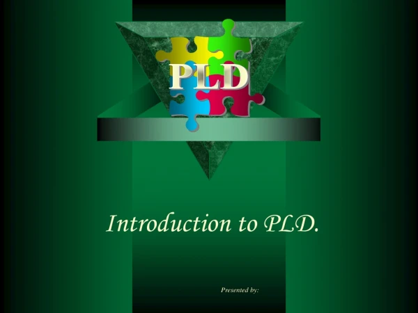
PLD Technology Basics. Basic PAL Architecture. CLK. OE. Fuse. D. Q. Q. Technology. The type of the configuration cell (Memory) defines the technology Bipolar metallic fuse, destroyed by prog., One-Time-Programmable (OTP) UV erasable (EPROM)

E N D
Basic PAL Architecture CLK OE Fuse D Q Q
Technology The type of the configuration cell (Memory) defines the technology • Bipolar • metallic fuse, destroyed by prog., One-Time-Programmable (OTP) • UV erasable (EPROM) • expensive window package or Plastic OTP, slow erase time • Electrical erasable (EEPROM) • multiple read/write cycles, In-System programmable,fast prog and erase, non-volatile • CMOS-Memory Cell • volatile, information lost after power-down, reconfigurable, very fast prog. Time, Configuration PROM needed • Antifuse, Vialink • open fuse element, programming forms an electrical connection, OTP, long prog times, low impedance interconnect
SPLDs use a programmable AND array and Clock/Input PAL fixed OR array to create several outputs in a sum-of-products form. SPLDs are commonly referred to as PALs. I/Os OR Gates Output Macrocells Dedicated Programmable AND Array Inputs From OR Gate I/O D Q These outputs can be either Q Clock combinatorial or registered in the macrocell. To AND Array PAL Architecture
Dedicated inputs I/Os PAL Block PAL Block I/Os Central Switch Matrix I/Os PAL Block PAL Block I/Os Clock/ Inputs The CPLD is an array of PAL-like devices, interconnected by a switch matrix. CPLD Architecture (1)
Clock Generator Clock/Input The CPLD architecture is more complex than the typical PAL in order to fully utilize the increased Central Switch Matrix logic capacity and additional I/O Allocator Logic Array I/O Output Output Switch Matrix routing matrices of the device. Cells Macrocell & Input Switch Matrix Product Term Enable From Output Switch To Output/Input From Logic I/O Matrix Switch Matrix Allocator D Q To Input Switch From Matrix Q D Clock From Clock Generator Generator The CPLD macrocell , although relatively similar to the The I/O Cell controls the flow of input PAL macrocell , has greater flexibility in routing its and output to and from the device. output to both the I/O Cells and Central Switch Matrix. CPLD Architecture (2)
MACH 4A Device Architecture PAL Block ClockGenerator Logic Arrayand Allocator Output/BuriedMacrocells OutputSwitchMatrix I/O Cells Clock/Input Pins I/O Pins InputSwitchMatrix Central Switch Matrix Macrocell Feedback DedicatedInput Pins I/O Pin Feedback (registered and non-registered) I/O Pins PAL Block PAL Block
Configurable Logic Block (CLB) Programmable Interconnect I/O Block Routing FPGAs utilize a channeled routing structure to connect blocks of configurable logic FPGA Architecture
Applications FPGA Variable Grain Architecture • Datapath Functions • Register Intensive • Narrow Gating • Pipelined Systems • Dense, Flexible • Low Power • Lower Speed than CPLDs Register Intensive Functions • Control Functions • High Speed • Wide Gating • State Machines • Address Decoding CPLD Combinatorial Functions
Measurement of Size and Density • SPLD • Measured by number of input/outputs (22V10) • ASIC • Available gates measured in 2-input equivalents • Usable gates typically 40 to 60 % • CPLD • Measured by macrocells (32 -1024) • Typical gate count ranges 1k to 40k • FPGA • Measured by gate count (1k to 100k) • Usable gates typically 50 to 60 % Attention! The Art of Gate Counting
In-System Programming Eases Prototyping • Easy development • Connect cable to PC, programmer or JTAG tester • Download software performs the following: • Bulk Erases the device (EE only) • Serializes the JEDEC (fusemap) file • “Bypasses” devices not being programmed • Shifts the JEDEC data into the device • Programs the JEDEC data into the configuration cells
Core Core Logic Logic TDI TDO TDO TDI TMS Boundary Scan TMS Boundary Scan Control Circuit TCK Control Circuit TCK TMS TCK TDO Boundary-Scan Cell (BSC) JTAG-Interface JTAG-Testing