Download
1 / 40
400 likes | 442 Views
Interactive Computer Graphics Implementation of a Renderer. James Gain and Edwin Blake Department of Computer Science University of Cape Town July 2002 jgain@cs.uct.ac.za. Map of the Lecture. Introduction and Discussion of Practicals Line Segment and Polygon Clipping

E N D
Interactive Computer GraphicsImplementation of a Renderer James Gain and Edwin Blake Department of Computer ScienceUniversity of Cape Town July 2002jgain@cs.uct.ac.za Collaborative Visual Computing Laboratory
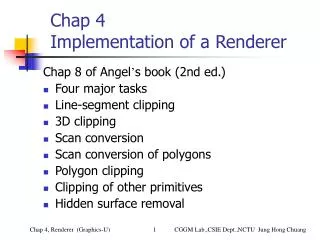
Map of the Lecture • Introduction and Discussion of Practicals • Line Segment and Polygon Clipping • Cohen-Sutherland and Liang-Barsky Clipping • Hidden Surface Removal • z-Buffer and Painter’s Algorithm • Scan Conversion • DDA and Bresenham Line Drawing • Flood Fill and Scan line Polygon Drawing • Aliasing and Antialiasing Interactive Computer Graphics Contents
Practical 1: Software Rendering • Overview: Emulate hardware rendering functionality by implementing it in software • Due Date: Wednesday 11 September • Requirements: • Polygon Scan Conversion using an Edge Table - Ch. 7 • Phong and Gouraud Shading - Ch. 6 • Coordinate Transformations - Ch. 4 • z-Buffer and Backface Removal - Ch. 7 • Extra details appear in handout from Foley, Van Dam, Feiner and Hughes: “Computer Graphics: Principles and Practice” Interactive Computer Graphics Contents
Practical 2: Scenegraph Construction • Overview: Design of Scenegraph nodes, allowing interactive hierarchical scene construction and visualization • Due Date: Monday 7 October • Requirements: (from Ch. 8 - Hierarchical and Object-Oriented Graphics & Ch. 3 - Input and Interaction) • Separator Node, Lighting and Texturing Node, Transform and Material Node, Model Node • Insert, update and traverse the scenegraph with mouse and keyboard input • Must display a visualization of the scenegraph Interactive Computer Graphics Contents
Practical 3: Simple Scenegraph Animation • Overview: Extend Scenegraph prac to include an animation node. Create a creature animation • Due Date: Friday 17 October • Requirements: • VRML Node - parse and display an object in VRML format • Animating Transform Node - allow animated rotation, translation and scaling, linked to a timer • Create an animating model • Opportunity to used a modelling package such as Teddy or Blender Interactive Computer Graphics Contents
Major Tasks of a Renderer • Modelling: • Produce sets of vertices that define geometric objects • Geometric Processing: • Determine which objects should appear and in what colour • Normalization Clipping Hidden Surface Removal Shading • Vertex-based: floating point processing in 3-D • Rasterization: • Generate frame buffer pixels by Scan Conversion • Pixel-based: integer processing in 2-D • Display: • Pixels are read from the frame buffer onto the CRT • Must overcome display artefacts through Antialiasing Interactive Computer Graphics Contents
Implementation Strategies • Must loop over pixels, geometric primitives, light sources. Which is the outer loop? • Image-Oriented (Sort-First): • for(each_pixel) assign_a_colour(pixel); • Need a data structure to indicate which objects affect which pixels • Requires only limited display memory but is computation intensive • Object-Oriented (Sort-Last): • for(each_object) render(object); • Supports a pipelined approach but is memory intensive An Object-Oriented Pipeline Interactive Computer Graphics Contents
Line-Segment Clipping • Task: Decide which primitives will appear on the display • Clipping relationship between primitive and view volume: • Accept if fits entirely inside • Reject (cull) if falls entirely outside • Clip if crosses the boundary • Placing Clipping in the pipeline: • Many possibilities - during modelling, in 3-D before projection, in 2-D after projection • OpenGL clips in 3-D Normalized Device Coordinates before final Orthographic Projection Interactive Computer Graphics Contents
Cohen-Sutherland Clipping I • Motivation: • Many line segments can be trivially accepted/rejected. Want to avoid intersection calculation in these cases • Seek to replace FP division with FP subs and bit ops • Create algorithm extensible to 3-D • Outcode: • Extend clipping edges to divide space in and around the clipping rectangle into nine regions • Each region has a unique 4-bit binary number o = b0b1b2b3 • If P = (x,y) then • Likewise b1 is y < ymin, b2is x > xmax, b3is x < xmin Interactive Computer Graphics Contents
Cohen-Sutherland Clipping II Exercise: What are the outcodes for A-J? • A = 0000; B = 0000 • C = 0000; D = 0010 • E = 0010; F = 0010 • G = 1001; H = 1000 • I = 0001; J = 1000 • Cases (line segment with endpoint outcodes o1, o2): • (o1 = o2 = 0) Both endpoints inside • (o1 ≠ 0, o2 = 0; or vice versa) One endpoint inside, the other out. Nonzero outcode indicates endpoint for shortening • (o1 & o2 ≠ 0) Do bitwise AND. If nonzero, both endpoints lie outside the same side discard • (o1 & o2 = 0) Both endpoints outside but on different clipping edges. Cannot tell from outcodes alone whether to shorten or discard Interactive Computer Graphics Contents
Liang-Barsky Clipping • Use parametric form: • Endpoints p1, p2; • p(a) = (1 - a) p1 + a p2 • a > 1 beyond p2 • a < 0 before p1 • Algorithm: • Find a1-4 where line intersects clipping edges (ymin, xmin, ymax, xmax) • Examine values and order of a to determine necessary clipping • Example: • 1 > a4 > a3 > a2 > a1 > 0, intersections in original line segment, innermost a2, a3 determine clipped segment • 1 > a4 > a2 > a3 > a1 > 0, intersections in original segment, reject because intersects top and bottom before intersecting left • Advantage: avoids multiple shortenings of segments, extensible to 3-D Interactive Computer Graphics Contents
Polygon Clipping • Often want to clip polygons against other polygons: • For display, shadow generation, hidden surface removal • Apply successive line clipping to a polygon • Concave Polygons: • Can increase the number of polygons or have edges that overlap • So, restrict to convex polygons by tesselating concave polygons • Sutherland-Hodgeman: • Treat line segment clipper as a black box which clips polygon against a line • Takes a pair of endpoints returns clipped endpoints • Can be linked into a pipeline Interactive Computer Graphics Contents
Clipping Other Primitives • Complex shapes are often represented by approximating polygons • Standard clippers apply but may be inefficient • Bounding Boxes: • Find the axis-aligned extents of the object, use this to trivially accept/reject object • Polynomial Curves and Surfaces: • Higher than cubic require numerical intersection tests • So, approximate by segments or polygons • Text: • Stroke - approximate with line segments and clip • Raster - scissor the bitmapped character in the frame buffer Interactive Computer Graphics Contents
Clipping in 3-D • Clipping against a 3-D bounding volume rather than a 2-D bounding region • Clipping algorithms (Cohen-Sutherland, Liang-Barsky and Sutherland-Hodgeman) extend to 3-D • Perspective Viewing: • Clip against the view frustum • BUT, easier to clip against a parallelepiped aligned with the axes • OpenGL: project to normalized orthographic view then clip • Lesson: in pipelining, always consider the process as a whole Interactive Computer Graphics Contents
Hidden-Surface Removal • Hidden Surface Removal (Visible Surface Determination) seeks to discover which objects are visible or obscured from the viewpoint • Object Space Approach: • Consider polygons A and B pair-wise and determine if: (a) B partially obscures A, (b) A partially obscures B, (c) A and B are completely visible, (d) B obscures A (or vice versa) • Image Space Approach: • Follows ray-casting approach • Ray leaves COP, passes through pixel and is intersected with polygon planes. Closest intersection gives visibility Interactive Computer Graphics Contents
Exercise: Complexity of HSR • Problem: • Determine the relative upper bound big-O complexity of object space and image space approaches, given k polygons and an n m display • Solution: • Object Space - Pick one of the k polygons and compare it pairwise to the other k-1, remove polygon from consideration and repeat = O(k2) • Image Space - For each of the n m pixels intersect and order the k polygons = O(mnk) = O(k) Interactive Computer Graphics Contents
Back-Face Removal • Streamline Hidden Surface Removal by first eliminating all back-facing polygons • Front facing if angle between polygon normal and view vector is -90 ≤ ≤90 • cos ≥ 0 n · v ≥ 0 • In normalized device coordinates: • Views are orthographic • v = (0,0,1) • Need only check the sign of nk Interactive Computer Graphics Contents
z-Buffer Algorithm I • Suited to pipelining and hardware • Works in image space but loops over polygons • z-buffer: • Holds current closest intersection depth • Same resolution as frame buffer • Number of bits per pixel gives depth resolution • Algorithm: • x, y: zbuffer(x, y) = MAX FOR each polygon for each pixel in polygon’s projection pz = polygons z-value at pixel coord (x,y) IF pz <= zbuffer(x, y) THEN zbuffer(x, y) = pz framebuffer(x, y) = polygons colour at pixel coord (x,y) Interactive Computer Graphics Contents
z-Buffer Algorithm II • Amount of incremental work is small • Rasterizing a polygon scan line by scan line • Polygon is in a plane ax + by + cz + d = 0 • Take two points (x1 , y1 , z1) and (x2 , y2 , z2) • Rewrite in differential form a ∆x + b ∆y + c ∆z = 0 ∆x = x2 - x1 , ∆y , ∆z similar • Across a scan line ∆y = 0 and ∆x is a constant step • ∆z = - c / a · ∆x No pre-sorting needed or object-object comparisons needed Interactive Computer Graphics Contents
Painter’s Algorithm • Render a scene using oil painter’s approach • Order polygons from back to front and render with new polygons overwriting old • Painting Order of Polygons: • IF no z overlap THEN Use depth sort order ELSEIF either x or y extents do not overlap THEN Use either order ELSEIF all vertices of P1 lie beyond the plane of P2 THEN render P1 before P2 • Two problems: • Cyclically overlapping polygons require cutting • Piercing polygons require clipping Interactive Computer Graphics Contents
Scan-Line Algorithm • Most efficient before advent of hardware • Rasterize one screen scan-line at a time • Exploit: • Incremental depth calculations for polygons on the scan-line • Coherence, since visibility status only changes at edges • Example: • line i , only one polygon ever active at a time so no depth comparisons needed • Line j , enter a (one poly), enter c (two polys active so check depth), leave d (one poly) , leave b (background) • Differs from z-buffer because it works on scan-lines rather than polygons Interactive Computer Graphics Contents
DDA Line Drawing • DDA = Digital Differential Analyzer, named after an early differential equation solver. • Generating a line is equivalent to solving a simple differential equation • Assume slope 0 ≤ m ≤ 1 • m = ∆y / ∆x => ∆y = m ∆x • Increase ∆x by 1 on each iteration ∆y = m • Algorithm: • for(i = x1; i <= x2; i++) { y += m; write_pixel(x, round(y), line_colour); } • For different slopes change the roles of x and y Interactive Computer Graphics Contents
Bresenham Line Drawing • Avoid floating point calculations • Again assume slope 0 ≤ m ≤ 1 • Next pixel can only be horizontal across or diagonally up • Use a decision variable d = a - b, where a = distance to upper pixel, b = distance to lower pixel • If d > 0 then across else diagonal • Replace with d = ∆x(a - b) for integer ops (does not affect sign of discriminator) • Calculating each successive pixel requires only an addition and a sign test Interactive Computer Graphics Contents
Bresenham Decision Variable • Compute d incrementally: • If y incremented on the previous step then a = a + 1 - m, b = m - 1 + b • If y NOT incremented previously then a = a - m, b = b + m • dk+1 = dk - { 2 ∆y if dk > 0 • { 2(∆y - ∆x) otherwise Interactive Computer Graphics Contents
Drawing Polygons: Inside-Outside Tests • To fill a polygon determine if a point P is inside or outside • Crossing or Odd-Even Test: • If P is inside then a ray emanating from P going to infinity will cross the polygon an odd number of times • Winding Test: • Fill the inside of non-simple polygons • Winding number = num times that a point is encircled by the edges of the polygon • Inside = winding num > 0 Filling with the odd-even test Interactive Computer Graphics Contents
Drawing Polygons: Flood Fill • Rasterize edges of polygons into frame buffer • Assume background is WHITE and drawing colour is BLACK • Grow colouring out from a seed point inside the polygon until an edge is encountered • Recursive Algorithm: • flood_fill(int x, int y) { if(read_pixel(x, y) == WHITE) { write_pixel(x, y, BLACK); flood_fill(x-1, y); flood_fill(x+1, y); flood_fill(x, y-1); flood_fill(x, y+1); } } Interactive Computer Graphics Contents
Scan-Line Polygon Drawing I • Generate pixels in the same order as they are displayed • Group pixels into contiguous spans on a scan line by finding where polygon edges intersect the scan line • The natural intersection order is based on processing successive polygon edges • But, would like intersections sorted first by scan line and then by increasing x on the scan line • With potentially many edge intersections an O(n log n) sort is burdensome • Use an incremental y-x algorithm Interactive Computer Graphics Contents
D F E Scan-Line Polygon Drawing II C B A EF DE • Use incremental calculations and exploit coherence • Create a global Edge Table (ET): • Edges are sorted into scan line buckets using the smallest vertex y value • Within a scan line bucket do an insertion sort on increasing x • Algorithm: use Active Edge Table (AET) to draw scan line y+1 • Edges in AET with ymax = y are deleted • Edges in ET with ymin = y+1 are added • Update the x-intersection values of active edges using an incremental approach • Fill pixels between pairs of active edge x-intersects yminx ymax yminx ymax 7 6 yminx ymax 5 CD 4 yminx ymax 3 FA 2 yminx ymax yminx ymax 1 AB BC 0 Interactive Computer Graphics Contents
Singularities • Polygon drawing breaks down if a scan line exactly intersects a vertex (singularity) • Cases: • Must count as 2 intersections • Must count as 1 intersection Solution: • Perturb any vertex that has an integer y value Interactive Computer Graphics Contents
Aliasing • Occurs when the sampling inherent in rendering does not contain enough information for an accurate image. Sampling Pixel Centres Rendered Image Original Scene Scanline Luminosity Sampled Signal Luminosity Signal Interactive Computer Graphics Contents
Effects of Aliasing • Common aliasing errors (called artefacts) are: jagged profiles, disappearing or improperfine detail, and disintegrating textures. Jagged Profiles Loss of Detail Interactive Computer Graphics Contents
Disintegrating Texture • The checkers on a plane should become smaller with distance. • But aliasing causes them to become larger and/or irregular. • Increasing resolutiononly moves the artefact closer to the horizon. Interactive Computer Graphics Contents
Antialiasing • Developed to combat aliasing • Applies to all types of aliasing – PSC, RT and temporal • Prefiltering: • Treat a pixel as an area. Calculate overlap of polygon with pixel. Costly • Postfiltering (supersampling): • Compute pixel colour by averaging multiple samples. Preferred Method • Sample the scene at n times the display resolution. For example, suppose the display resolution is 512x512. Sampling at three times the width and three times the height of the display resolution would yield 1536x1536 samples • A filter provides the weights used to compute the average Interactive Computer Graphics Contents
Prefiltering No Antialiasing Prefiltering Interactive Computer Graphics Contents
Postfiltering • Sampling: take jittered, regular or random samples. • Averaging: use an filter to assign weights to each sample. Sum all the weighted samples to obtain a pixel. Jittered Regular Interactive Computer Graphics Contents
Filtering Example Interactive Computer Graphics Contents
Antialiasing Examples Interactive Computer Graphics Contents