Download
1 / 60
690 likes | 1.12k Views
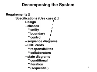
6. System Design: Decomposing the System. Outline. Design System Design Activities Determine Design Goals System Design Concepts Software Architecture Pattern. 1. Design. 1.1 Design.

E N D
Outline • Design • System Design Activities • Determine Design Goals • System Design Concepts • Software Architecture Pattern
1.1 Design “There are two ways of constructing a software design: One way is to make it so simple that there are obviously no deficiencies, and the other way is to make it so complicated that there are no obvious deficiencies.” - C.A.R. Hoare
1.2 Why is Design so Difficult? • Analysis: Focuses on the application domain • Design: Focuses on the implementation domain • Design knowledge is a moving target • The reasons for design decisions are changing very rapidly • Halftime knowledge in software engineering: About 3-5 years • What I teach today will be out of date in 3 years • Cost of hardware rapidly sinking • “Design window”: • Time in which design decisions have to be made
1.3 The Purpose of System Design • Bridging the gap between desired and existing system in a manageable way • Use Divide and Conquer • We model the new system to be developed as a set of subsystems Problem New System Existing System
1.4 Viewpoint Change Do the right things Do the things right How What
1.5 Input and Output • Design goals • Software architecture • Boundary use cases • A set of nonfunctional requirements • use case model • sequence diagrams
Overview System Design I (This lecture) 0. Overview of System Design 1. Design Goals 2. Subsystem Decomposition System Design II: Addressing Design Goals (next lecture) 3. Hardware/Software Mapping 4. Persistent Data Management 5. Global Resource Handling and Access Control 6. Software Control 7. Boundary Conditions
nonfunctional requirements Analysis dynamic model analysis object model System design design goals subsystem decomposition Object design object design model
How to use the results from the Requirements Analysis for System Design • Nonfunctional requirements => • Activity 1: Design Goals Definition • Functional model => • Activity 2: System decomposition (Selection of subsystems based on functional requirements, cohesion, and coupling) • Object model => • Activity 3: Hardware/software mapping • Activity 4: Persistent data management • Dynamic model => • Activity 5: Global resource handling • Activity 6: Software control • Subsystem Decomposition • Activity 7: Boundary conditions
Section 1. Design Goals • Good documentation • Well-defined interfaces • User-friendliness • Reuse of components • Rapid development • Minimum # of errors • Readability • Ease of learning • Ease of remembering • Ease of use • Increased productivity • Low-cost • Flexibility • Reliability • Modifiability • Maintainability • Understandability • Adaptability • Reusability • Efficiency • Portability • Traceability of requirements • Fault tolerance • Backward-compatibility • Cost-effectiveness • Robustness • High-performance
Developer/ Maintainer Relationship Between Design Goals End User Functionality User-friendliness Ease of Use Ease of learning Fault tolerant Robustness Low cost Increased Productivity Backward-Compatibility Traceability of requirements Rapid development Flexibility Runtime Efficiency Reliability Portability Good Documentation Client (Customer, Sponsor) Minimum # of errors Modifiability, Readability Reusability, Adaptability Well-defined interfaces
Typical Design Trade-offs • Functionality vs. Usability • Cost vs. Robustness • Efficiency vs. Portability • Rapid development vs. Functionality • Cost vs. Reusability • Backward Compatibility vs. Readability
How do we get the Design Goals? Let’s look at a small example • Current Situation: • Computers must be used in the office • What we want: • A computer that can be used in mobile situations.
Identify Current Technology Constraints Direction where the user looks is irrelevant Single Output Device Fixed Network Connection Location of user does not matter Precise Input
Direction where the user looks is irrelevant Single Output Device Fixed Network Connection Location of user does not matter Precise Input Generalize Constraints using Technology Enablers Direction where the user looks is relevant Multiple Output Devices Dynamic Network Connection Location-based Vague Input
Establish New Design Goals • Mobile Network Connection • Multiple Output Devices • Location-Based • Multimodal Input (Users Gaze, Users Location, …) • Vague input
Sharpen the Design Goals • Location-based input • Input depends on user location • Input depends on the direction where the user looks (“egocentric systems”) • Multi-modal input • The input comes from more than one input device • Dynamic connection • Contracts are only valid for a limited time • Is there a possibility of further generalizations? • Example: location can be seen as a special case of context • User preference is part of the context • Interpretation of commands depends on context
Part System 4.1 Subsystems and Classes • Subsystem • Collection of classes, associations, operations, events and constraints that are interrelated • Seed for subsystems: UML Objects and Classes. * * Class Subsystem parts
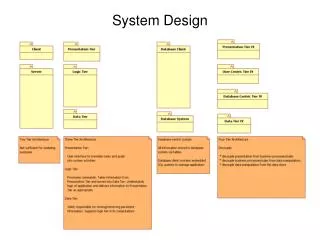
The subsystem decomposition: (1) Logical component; (2) Physical Component
4.2 Services and Subsystem Interfaces • Service: A set of related operations that share a common purpose • Notification subsystem service: • LookupChannel() • SubscribeToChannel() • SendNotice() • UnscubscribeFromChannel() • Services are defined in System Design • Subsystem Interface: Set of fully typed related operations. Also called application programmer interface (API) • Subsystem Interfaces are defined in Object Design
Services and Subsystem Interfaces • Service: A set of related operations that share a common purpose • Notification subsystem service: • LookupChannel() • SubscribeToChannel() • SendNotice() • UnscubscribeFromChannel() • Services are defined in System Design • Subsystem Interface: Set of fully typed related operations. Also called application programmer interface (API) • Subsystem Interfaces are defined in Object Design
Modeling Authoring Workorder Repair Inspection Augmented Reality Workflow Subsystem Decomposition Example Is this the right decomposition or is this too much ravioli?
Definition: Subsystem Interface Object • A Subsystem Interface Object provides a service • This is the set of public methods provided by the subsystem • The Subsystem interface describes all the methods of the subsystem interface object • Use a Facade pattern for the subsystem interface object(Later chapter)
System as a set of subsystems communicating via a software bus Authoring Modeling Workflow Augmented Reality Inspection Repair Workorder A Subsystem Interface Object publishes the service (= Set of public methods) provided by the subsystem
Repair Inspection Authoring Augmented Reality Workflow Modeling A 3-layered Architecture
Tournament Component Management User Management Tournament Statistics User Directory User Interface Session Management Advertisement Another Example: ARENA Subsystemdecomposition
Tournament Component Management User Management Tournament Statistics User Directory User Interface Session Management Advertisement Services provided by ARENA Subsystems Manages advertisement banners and sponsorships. Administers user accounts Manages tournaments, applications, promotions. For adding games, styles, and expert rating formulas Stores user profiles (contact & subscriptions) Stores results of archived tournaments Maintains state during matches.
4.3 Coupling and Cohesion • Goal: Reduction of complexity while change occurs • Cohesion measures the dependence among classes • High cohesion: The classes in the subsystem perform similar tasks and are related to each other (via associations) • Low cohesion: Lots of miscellaneous and auxiliary classes, no associations • Coupling measures dependencies between subsystems • High coupling: Changes to one subsystem will have high impact on the other subsystem (change of model, massive recompilation, etc.) • Low coupling: A change in one subsystem does not affect any other subsystem • Subsystems should have as maximum cohesion and minimum coupling as possible: • How can we achieve high cohesion? • How can we achieve loose coupling?
4.4 Partitions and Layers Partitioning and layering are techniques to achieve low coupling. A large system is usually decomposed into subsystems using both, layers and partitions. • Partitions vertically divide a system into several independent (or weakly-coupled) subsystems that provide services on the same level of abstraction. • A layer is a subsystem that provides subsystem services to a higher layers (level of abstraction) • A layer can only depend on lower layers • A layer has no knowledge of higher layers
Layer 1 Layer 2 Layer 3 Subsystem Decomposition into Layers • Subsystem Decomposition Heuristics: • No more than 7+/-2 subsystems • More subsystems increase cohesion but also complexity (more services) • No more than 4+/-2 layers, use 3 layers (good)
Relationships between Subsystems • Layer relationship • Layer A “Calls” Layer B (runtime) • Layer A “Depends on” Layer B (“make” dependency, compile time) • Partition relationship • The subsystems have mutual but not deep knowledge about each other • Partition A “Calls” partition B and partition B “Calls” partition A
Virtual Machine • Dijkstra: T.H.E. operating system (1965) • A system should be developed by an ordered set of virtual machines, each built in terms of the ones below it. Problem VM1 C1 C1 C1 attr attr attr opr opr opr C1 C1 VM2 attr attr opr opr C1 VM3 C1 attr attr opr opr C1 VM4 attr opr Existing System
Virtual Machine • A virtual machine is an abstraction • It provides a set of attributes and operations. • A virtual machine is a subsystem • It is connected to higher and lower level virtual machines by "provides services for" associations. • Virtual machines can implement two types of software architecture • Open and closed architectures.
C1 C1 C1 C1 C1 C1 C1 C1 C1 VM1 attr attr attr attr attr attr attr attr attr op op op op op op op op op VM2 VM3 VM4 Closed Architecture (Opaque Layering) • Any layer can only invoke operations from the immediate layer below • Design goal: High maintainability, flexibility
C1 C1 C1 C1 C1 C1 C1 C1 C1 attr attr attr attr attr attr attr attr attr op op op op op op op op op Open Architecture (Transparent Layering) • Any layer can invoke operations from any layers below • Design goal: Runtime efficiency VM1 VM2 VM3 VM4
Properties of Layered Systems • Layered systems are hierarchical. They are desirable because hierarchy reduces complexity (by low coupling). • Closed architectures are more portable. • Open architectures are more efficient. • If a subsystem is a layer, it is often called a virtual machine. • Layered systems often have a chicken-and-egg problem • Example: Debugger opening the symbol table when the file system needs to be debugged
OSI model Packages and their Responsibility • The Physicallayerrepresentsthehardwareinterfacetothenet-work. Itallowstosend()andreceivebitsover a channel. • The Datalinklayerallowstosend andreceiveframeswithouterrorusingtheservicesfromthePhysicallayer. • The Network layerisresponsibleforthatthedataarereliablytransmittedandroutedwithin a network. • The Transport layerisresponsibleforreliablytransmittingfrom end to end. (This istheinterfaceseenby Unix programmerswhentransmittingoverTCP/IP sockets) • The Sessionlayerisresponsibleforinitializing a connection, includingauthentication. • The Presentationlayerperformsdatatransformationservices, such asbyteswappingandencryption • The Applicationlayeristhesystemyouaredesigning (unlessyoubuild a protocolstack). The applicationlayerisoftenlayereditself.
Another View at the ISO Model • A closed software architecture • Each layer is a UML package containing a set of objects
Application Object Presentation CORBA Session Transport Socket TCP/IP Network DataLink Physical Ethernet Wire Middleware Allows Focus On The Application Layer
5.1 Software Architectural Styles • Subsystem decomposition • Identification of subsystems, services, and their relationship to each other. • Specification of the system decomposition is critical. • Patterns for software architecture • Client/Server • Peer-To-Peer • Repository • Model/View/Controller • Pipes and Filters
5.2 Client/Server Architectural Style • One or many servers provides services to instances of subsystems, called clients. • Client calls on the server, which performs some service and returns the result • Client knows the interface of the server (its service) • Server does not need to know the interface of the client • Response in general immediately • Users interact only with the client
Often used in database systems: • Front-end: User application (client) • Back end: Database access and manipulation (server) • Functions performed by client: • Customized user interface • Front-end processing of data • Initiation of server remote procedure calls • Access to database server across the network • Functions performed by the database server: • Centralized data management • Data integrity and database consistency • Database security • Concurrent operations (multiple user access) • Centralized processing (for example archiving)
Design Goals for Client/Server Systems// • Service Portability • Server can be installed on a variety of machines and operating systems and functions in a variety of networking environments • Transparency, Location-Transparency • The server might itself be distributed (why?), but should provide a single "logical" service to the user • Performance • Client should be customized for interactive display-intensive tasks • Server should provide CPU-intensive operations • Scalability • Server should have spare capacity to handle larger number of clients • Flexibility • The system should be usable for a variety of user interfaces and end devices (eg. WAP Handy, wearable computer, desktop) • Reliability • System should survive node or communication link problems