Download
1 / 27
270 likes | 405 Views
Solid State Storage System for the International Space Station. Jake Berlier David Jacob Dr. Jerry Tucker Dr. James M. McCollum. Outline. Introduction Orion Project Solid State Storage System Overview Progress to Date Conclusion. Introduction.

E N D
Solid State Storage System for the International Space Station Jake Berlier David Jacob Dr. Jerry Tucker Dr. James M. McCollum
Outline • Introduction • Orion Project • Solid State Storage System Overview • Progress to Date • Conclusion
Introduction • Goal: Design and implement a solid state storage system with data redundancy for space-applications • Aerospace Innovations Inc. contract for NASA • Tom Johnson, Bob Akamine • Supporting Orion Project
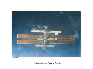
Constellation: Ares and Orion Spacecraft • Phase-out older space Shuttle and phase-in new Ares and Orion spacecraft • This project will be incorporated in a system that will capture telemetry and video data • Train “auto-docking” with International Space Station Atlantis Space Shuttle Images from: http://www.nasa.gov/ Orion Crew Vehicle and Ares Launch Vehicle
Requirements • Record data to Solid State drives • Write speed faster than Aurora • Data redundancy and recovery • RAID 6 encoding and decoding • CRC • 2 Drive recovery may be done on the ground • 2 different data sources • Must be able to switch so that the key data is collected • Radiation Hardening/Resistance • Solid State Drives
Secondary Goals • Reading from drives • Single error correction • Double error correction
Xilinx ML410 FPGA Selection and Personality Module • ML410 FPGA was selected over newer FPGAs • Radiation resistance (latchup) • Functionality • Personality Module • More SATA ports • Development GPIO Image from: www.xilinx.com
System Overview • Aurora Interface • SATA Controller • PLB Architecture • Power PC Aurora Interface Aurora Command Interface S S PPC Aurora PHY M PLB S Interrupt Controller DATA RECORDER Aurora Data Interface Aurora PHY S M S SATA Controller M HD HD HD
Data Recorder (outside scope of project) • Two data sources • Primary and secondary • Aurora Interface
Aurora Interface (outside scope of project) • Open IP Core (Free!) • Differential signaling • High speed (multiple Giga-bits) • Command vs. Data • User Flow Control with embedded commands • Separation of Data from Command Aurora Interface Aurora Command Interface S Aurora PHY M Aurora Data Interface Aurora PHY S M
SATA IP Core SATA IP Core SATA IP Core SATA IP Core SATA IP Core SATA IP Core SATA IP Core SATA IP Core HD HD HD HD HD HD HD HD SATA/RAID Controller PLB • PLB Interface • Master • Slave • SATA IP Core/ Supporting HDL • Data Buffer • RAID 6 Encoding/ Decoding M S Master FSM Slave Registers and Address Decoder “Word Stripe” Buffer RAID Encode/Decode
PLB Architecture • Master Components • Burst-line Support • Slave Components • PPC • Control/Status Registers • Interrupts PLB S Interrupt Controller
Role of Power PC and Chipscope • Power PC • Top-Level Control • Debugging and Development • Compile time vs. Build time • Chipscope • View status of signals during operation
Spring/Summer Development Timeline Single Drive Aurora System Six Drive Aurora System RAID 6 System with Secondary Goals Working SATA PHY Software SATA Controller System Requirement Analysis MGT Side-A January February March April May June July RAID Planning RAID Simulation Testing (Proof of Concept) Aurora-SATA Interface Single Drive SATA Dual Drive Aurora System RAID 6 System
HOST DEVICE Application Layer Application Layer Command Layer Command Layer Transport Layer Transport Layer Link Layer Link Layer Physical Layer Physical Layer Physical Connection(SATA Port) SATA Overview • Application Layer • High-level interface (Wishbone) • Control registers, etc… • Command Layer • FSM for parsing commands • Transport Layer • Frame Information Structure (FIS) • Buffering • Error Reporting • Flow Control • Link Layer • Scrambler • 8b-10b encoding • CRC • Communication Primatives • Physical Layer • Handles physical transmission of differential signals SATA Topology
ASICS WS SATA IP Core • Proprietary • Implements Application, Command, Transport, and Link layers (no PHY) • Interface: • Application layer - Wishbone • PHY connections • External buffer WB FSM ASICS SATA Core FIFO PHY HD
SATA Physical Layer • XAPP 716SATA Host Controller (Linux over Ethernet) • Implements a basic SATA physical layer using the ASICS WS core • Source code (minus the ASICS WS core) is publicly available from Xilinx • Physical layer uses MGT
Multi-Gigabit Transceiver (MGT) • High-speed serial data connections • Functionality: • 8b-10b encoding/decoding • Scrambling • PLL/clock synchronization • DRP - threshold detection not automatic • Side A vs. Side B of MGT • Can accommodate two SATA connections
SATA – Software to Hardware (Wishbone Interface) • Currently, SATA works with software control from the Power PC • Slow • Serial Writing/Reading • Easier and faster for initial implementation • Move to hardware in stages: • Wishbone interface • Multiple Hard Drives • RAID • Etc…
Current Stage of Development: PLB Master Burst to SATA in Hardware • Master vs. Slave • Speed improvement through Master Burst • Will enable throughput testing for read and write • Data for single drive, estimate for multiple drives
2-Drive System • Implementation for both sides of MGT • Currently, only one side is connected • Constraints • Control for multiple drives (drive-pairs) • FSM • Management of critical resources • Digital Clock Managers • Better estimate of resource usage
6-Drive System • Control for multiple drives (for entire system) • 6 data drives • Word Stripe buffer • Power consumption estimation • Throughput testing • Maximum speed of system
8-Drive System with RAID • Raid encoding/decoding • Working system! • Primary goal is writing • Speed critical • Secondary goals: • Read with single error correction on the fly • Read with double error correction using CRC • Higher speed is more desirable
RAID Overview • Encoding on the fly • Single Error Correction for reads (on the fly) • Double Error Correction for reads (on Ground or during mission)
Other Project Milestones • Solid State Drive Testing • Radiation Testing
Conclusion • Reconfigurable Design • Plan for requirements • Debugging and incremental development with Power PC and Chipscope • Working system delivered by the end of June