Download
1 / 7
70 likes | 75 Views
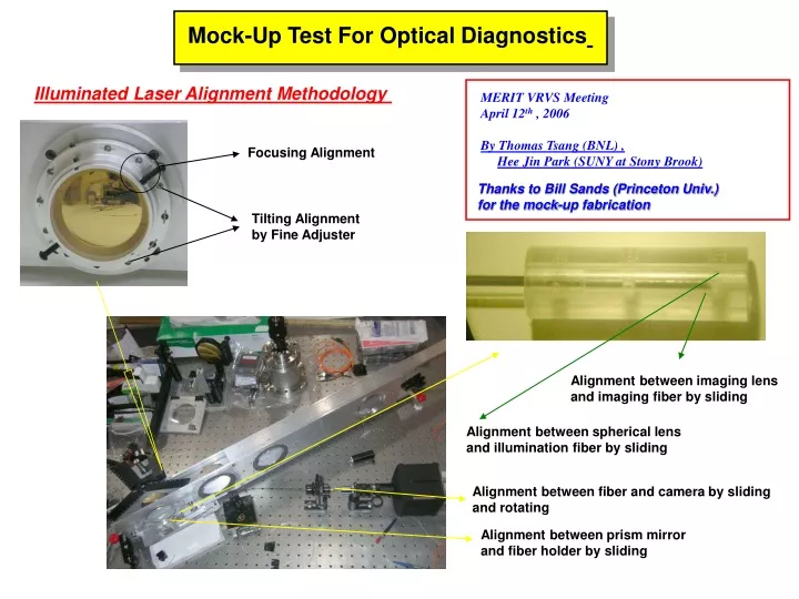
Mock-Up Test For Optical Diagnostics. Illuminated Laser Alignment Methodology. MERIT VRVS Meeting April 12 th , 2006 By Thomas Tsang (BNL) , Hee Jin Park (SUNY at Stony Brook). Focusing Alignment. Thanks to Bill Sands (Princeton Univ.) for the mock-up fabrication. Tilting Alignment

E N D
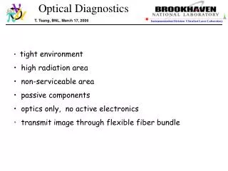
Mock-Up Test For Optical Diagnostics Illuminated Laser Alignment Methodology MERIT VRVS Meeting April 12th , 2006 By Thomas Tsang (BNL) , Hee Jin Park (SUNY at Stony Brook) Focusing Alignment Thanks to Bill Sands (Princeton Univ.) for the mock-up fabrication Tilting Alignment by Fine Adjuster Alignment between imaging lens and imaging fiber by sliding Alignment between spherical lens and illumination fiber by sliding Alignment between fiber and camera by sliding and rotating Alignment between prism mirror and fiber holder by sliding
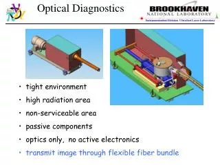
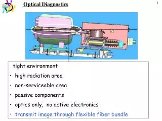
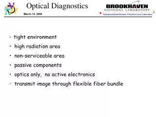
Design Principle & Fiber Holder Design 0.07’’ Less than 6’’ (Secondary Containment ID) Imaging Lens NA angle > 60° Ø=1mm (Tested) Ø=1.8mm(Test Scheduled) Spherical Lens 0.5mm (Tested) 1mm (Test Scheduled) Gasket : t= 2 X 1/32’’ Mineral Particles with Acrylic Buna-N WD=±0.7’’ F=4.9’’ Ø=100mm t=6mm Sapphire Window 0.75’’ Screw Type : #0-80 Illumination fiber should be tightly inserted into hole in order for the fiber and lens to be aligned well.
Working Principle : Shadowgraph Technique This technique is valuable when visualizing flows in which density differences occur naturally or are artificially induced. When used quantitatively, this technique can often be used to determine density, pressure, and/or temperature variations in the flow. From these, other properties of the flow field (e.g., laminar versus turbulent nature of the motion, boundary layer thickness, shock angles, points of separation, and reattachment) can be inferred. It integrates the quantity measured over the length of the light beam. For this reason it is well suited to measurements in two-dimensional fields, where there is no index of refraction or density variation in the field along the light beam, If large gradients of density are present, as in a shock wave or a flame, shadowgraph pictures can be very useful. Quantitative measurements of such things as shock angles and the location of boundary-layer transition can be made. In a shadowgraph system the linear displacement of the perturbed light is measured, rather than the angular deflection. The contrast would have to be measured accurately, for example, integrated twice to determine the density distribution. n : index of refraction : index of refraction of ambient air For gas or transparent liquid media, it is useful.
Stationary Image Analysis CW Light Illuminated 65 ms/frame Sumitomo Imaging Fiber The illuminated laser was not covered fully by the prism mirror when we try to get the largest field of view. To prevent the asymmetry of the field of side view, the center-center between prism mirror and fiber holder set will be misaligned artificially. More than 5.5cm Field Of View can be measured at the center of captured image. Imaging Fiber Defect : Stain or Crack, etc It will be removed if the surface of fiber can be polished well.
Moving Image Analysis NIR Pulsed Laser Illuminated 10 µs/frame Sumitomo Imaging Fiber Measured Linear Velocity ≈ 40m/s
Things To Do 1. The modified 4 different types of fiber holder are now under fabrication. 2. Ø=1.8mm imaging lens will be tested to see the effect of the field of view as well as illumination intensity with combination of ø=0.5mm & ø=1mm spherical ball lens. 3. The hole for the fiber bunch following fiber holder will be modified to let the fiber bunch bend within the allowable bending radius (40mm) 4. Polishing process of Imaging fiber will be investigated before we polish the actual 10m long imaging fiber. 5. The retro-reflecting mirror assembly for 4 viewport is already now under fabrication. One whole plate for 4 viewport will be designed after modification based on the mock-up test result. 6. Finally, the performance of 4 individual viewport must be tested simultaneously with the actual length of imaging fiber and illumination fiber.