Download
1 / 16
280 likes | 658 Views
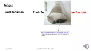
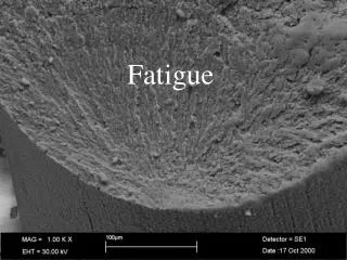
An Experimental Study and Fatigue Damage Model for Fretting Fatigue. Aditya A. Walvekar Ph.D. Research Assistant. Outline. Motivation Objective Fretting Fatigue Test Rig Experimental results Fatigue Damage Model Fretting Fatigue Life Predictions Summary Future work. Motivation.

E N D
An Experimental Study and Fatigue Damage Model for Fretting Fatigue Aditya A. Walvekar Ph.D. Research Assistant
Outline • Motivation • Objective • Fretting Fatigue Test Rig • Experimental results • Fatigue Damage Model • Fretting Fatigue Life Predictions • Summary • Future work
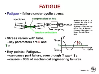
Motivation • Fretting is associated with the small amplitude relative oscillatory motion between two solid surfaces in contact • Fretting fatigue is a damage mechanism observed in a machine components subjected to fretting in tandem with fluctuating bulk stresses • If the material is concurrently subjected to partial slip fretting and fluctuating bulk loading, stress concentration at the contact region results in premature nucleation and acceleration of crack growth when compared to fatigue situations without fretting Fretting Fatigue Test configuration* * ASTM E2789-10 : Standard Guide for Fretting Fatigue Testing
Objective • Experimental investigation of the fretting fatigue behavior of AISI 4140 vs. Ti-6-4 in a cylinder-on-flat contact configuration • Analyze the effect of bulk stress on the fretting fatigue life at a fixed normal load • Analyze the crack propagation i.e. crack length vs. number of cycles • Develop a model based on damage mechanics to analytically investigate fretting fatigue • Incorporate Voronoi tessellation to account for the randomness of the material microstructure and conduct life variability studies
Fretting Fatigue Test Rig • A fretting test fixture was designed and developed which was coupled with an MTS machine to impose the fretting fatigue damage Fretting fatigue fixture mounted on MTS machine Schematic of fretting fatigue test rig
Experimental Results Picture of contact pads and specimen assembled in the test rig Fretting and bulk stress vs. life • Fretting fatigue tests were conducted in a cylinder-on-flat contact configuration under completely reversed constant-amplitude axial load control conditions (R = -1) at 5 Hz frequency • The amplitude of the axial bulk stress was varied from 100 MPa to 600 MPa while the normal force was held constant at 11 kN (peak Hertzian pressure of 3 GPa) • Fretting stress () at the trailing edge of the contact is calculated using –
Determination of estimated crack initiation (Bulk Stress = 348 MPa) • Estimated crack initiation life – 34000 cycles • First visible crack observed at 33420 cycles with a length of 765 microns Pictures of the crack growth taken as the test is running (Bulk Stress = 348 MPa) Crack length vs. life cycles (Bulk Stress = 348 MPa)
Coefficient of Friction Measurement • A fretting test was performed in the gross slip regime to determine the coefficient of friction • The specimen was only held with the bottom grip while the top end of specimen was free • Completely-reversed sinusoidal displacement at a frequency of 1 Hz was applied to the specimen Fretting wear test at gross slip (displacement amplitude = 150 μm)
Finite Element Model • Randomness of material microstructure topology is simulated using Voronoi tessellation to account for the variability in fretting fatigue life • The sinusoidal reaction stress with amplitude “σreaction” is applied on the left edge of the lower body in phase with the bulk stress to model FT Finite element mesh using Voronoi Tessellation The geometry and the applied loading conditions (a = 365 μm) FT/FNobtained from experiments and FE model
Model Validation • To validate the stress distribution obtained from the FE model, shear and tangential stress distribution on the contact surface were compared with the analytical solution Comparison of shear stress and normalized tangential stress distribution on the contact surface at the positive peak of the fretting cycle obtained using FE model and analytical solution. (Bulk Stress = 400 MPa)
Fatigue Damage Model • In order to introduce randomness into the life predictions, the alternating normal stress ( acting along the Voronoi grain boundary during the fretting cycle is assumed to cause damage • Damage evolution rate equation – • Alternating Normal Stress – • and are the maximum and the minimum normal stresses acting on the Voronoi grain boundary during a fretting cycle Stresses resolved along the Voronoi grain boundaries
Variation of Elasticity Modulus • Increase in the internal damage as the fatigue cycles progress, manifests as the reduction in the modulus of elasticity. Elastic modulus of the damaged element - Rearranging, • Accurate strain measurements are important for measuring elasticity modulus so a strain gauge was installed on in the constant cross sectional area region of the specimen Stress vs. strain plot at various cycles for the variation of elasticity modulus test
Evaluation of Damage Parameters • The peak in the tensile stress at the trailing edge of the contact () drives the crack initiation in fretting fatigue. The critical stress component causing the damage is assumed to be the fretting stress • The damage parameters σRand m were evaluated using the maximum fretting stress and fretting fatigue life data from experiments. Applying a power law curve fit to the data: where, 3 Integrating, Rearranging, • Comparing Coefficients –
Fretting Fatigue Life Predictions • Fatigue Damage model was used for predicting fretting fatigue life of 30 randomly generated microstructure domains for four different loading conditions • Degree of scatter is quantified using two-parameter Weibull probability distribution Comparison between the fretting fatigue lives from model and experiments Material properties used in the analysis Loading conditions applied and predicted Weibull slope and strength parameters Weibull probability plot for fretting fatigue lives
Summary • A fretting fixture was designed, built and used with an MTS 810 machine simulating the fretting fatigue in a cylinder-on-flat configuration • For a fixed contact pressure, the fretting fatigue life decreased with increasing bulk stress • A fatigue damage finite element model was proposed to replicate the fretting fatigue experiments and numerically estimate the fretting fatigue life • The fretting fatigue lives predicted by the fatigue damage model are in good agreement with the experimental results • The predicted fatigue life data displayed a larger degree of scatter for the lower bulk stress when the contact pressure is fixed
Future Work • Modify the fatigue damage model to include crack propagation • Evaluate the effects of shot-peening, residual stress on Fretting Fatigue behavior • Analyze the effects of inclusions and voids on the fretting fatigue life • Incorporate plasticity in the fatigue damage model