Download
1 / 29
300 likes | 332 Views
IEP on Design Verification and Hardware Security NIT, Rourkela. Memory Interface Example. Concurrency and Control.

E N D
IEP on Design Verification and Hardware Security NIT, Rourkela Memory Interface Example
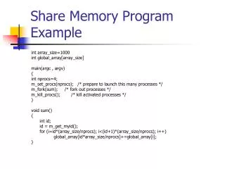
Concurrency and Control • Concurrency basically allows you to spawn off multiple parallel processes from a parent process. It brings power and flexibility to your verification environment, which inherently requires the execution of many processes in parallel, both for efficiency and smarter inter-process interaction. • For inter-process communication, constructs called mailboxes allow any process to send a message to any other process. A receiving process can also synchronize with a sending process by waiting for its message. • Constructs called semaphores prevent several parallel processes from trying to access a common resource, such as a signal, by allowing access to only one process at any time. • Named events in processes are triggered using -> operator. These triggered events are received by other processes with the help of event control constructs in order to synchronize with the triggering processes. • Other process-control mechanisms are also provided to help processes wait either on specific variables or until the completion of their child processes.
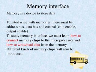
Memory System Courtesy: www.synopsys.com
Memory System • The design used in this tutorial is a simple memory system for a two CPU machine. It consists of a system bus, a centralized round-robin arbiter, and a memory controller that controls four static SRAM devices. • Notice that the blocks labelled CPU0 and CPU1 are shaded. This is to indicate that these blocks are not part of the system under test, but rather these blocks will be modeled within the SystemVerilog testbench. The signals shown between the CPUs and the rest of the system form the interface between the system under test and the “outside world.” • The memory system consists of the SRAMs, the Memory Controller, and the Arbiter. These are all defined in the HDL files of each sub-module. The approach used to verify the memsys system is similar to most project verification flows: Courtesy: www.synopsys.com
Arbiter • The arbiter implements a round-robin arbitration algorithm between two CPUs. Each CPU can drive a request input signal (request[0] or request[1]). • The arbiter queues the requests and determines which CPU will gain access to the system bus. The arbiter grants this access by asserting one of the grant output signals (grant[0] or grant[1]). • While the grant signal is asserted for a given CPU, the CPU continues to assert its request signal so that both the grant and request signals for the CPU remain high while the CPU accesses the system bus. • Once the CPU is done, it de-asserts its request signal and, on the subsequent clock cycle, the arbiter de-asserts its grant signal. With all the signals de-asserted, the arbiter can continue with the next request. Courtesy: www.synopsys.com
Verifying Arbiter • Reset Verification: - $write("Task reset_test: asserting and checking reset\n"); reset_p <= 1; repeat (2) @(posedge clk); reset_p <= 0; request_p <= 2'b00; expect(@(posedgeclk) grant_p== 2'b00); • Test For Simple Request by CPU0: - To test requests are handled correctly for CPU0, drive bit 0 of the request signal and then monitor bit 0 of the grant signal. Finally, de-assert both bits of the request signal and check that both bits of the grant signal are properly de-asserted. @(posedge clk) request_p <= 2'b01; @(posedge clk); expect(@(posedge clk) grant_p == 2'b01); @(posedge clk) request_p <= 2'b00; @(posedge clk); • expect(@(posedge clk) grant_p == 2'b00);
Sequenced Request Verification • Assert both request signals and check that the correct grant is asserted (depends on which grant was previously asserted) • Release the granted request and check that both grants are released • Then check that the other grant is asserted • Finally release the other request and check that both grants are released @(posedge clk) request_p <= 2'b11; @(posedge clk); expect(@(posedge clk) grant_p == 2'b01); request_p <= 2'b10; expect(@(posedge clk) ##[0:2] grant_p == 2'b10); request_p <= 2'b00; repeat (2) @(posedge clk); assert(grant_p == 2'b00); Courtesy: www.synopsys.com
Verifying the reset task reset_test; $write("Task reset_test: asserting and checking reset\n"); reset_p <= 1; repeat (2) @(posedge clk); reset_p <= 0; request_p <= 2'b00; expect(@(posedge clk) grant_p == 2'b00) else $display($time, " Failed"); endtask Courtesy: www.synopsys.com
Memory Controller • The CPU accesses the bus through the arbiter. Once the CPU has access, it puts its request on the system bus. The memory controller acts on this request by reading data from the SRAM devices and returning data when necessary. • The memory controller reads requests from the system bus and generates control signals for the SRAM devices attached to it. • For read requests, the controller reads data and transfers it back to the bus and the CPU making the request. The address bus is 8 bits wide, which creates an address space of 256 bytes. • The controller supports up to 4 devices, allocating a maximum of 64 bytes of memory to each. Courtesy: www.synopsys.com
Memory Controller Interaction memory Controller Read Operation Timing Diagram Memory Controller Write Operation Timing Diagram Courtesy: www.synopsys.com
Verifying the Memory Controller To completely check the functionality of the memory controller, you have to perform a series of tests: - First, verify the controller’s reset by writing a task. Then, write tasks to check the read and write operations of the controller. Also check the integrity of the read and write operations. Finally, check the address map (all 256 addresses) exhaustively for the read and write functions. Rather than connecting the RTL models of the memory to the controller, model the behavior of the four different memory devices in the testbench.
Controller Interface Courtesy: www.synopsys.com
Controller Reset Verification Resetting the Controller: Verifying the Reset: - Courtesy: www.synopsys.com
Invoking the Tasks Courtesy: www.synopsys.com
Driving the System bus for Read and Write Operations • Read Operation: - • This task is passed the argument adx. It then drives the busAddr signal to that value. Finally, it drives the busRdWr_N and adxStrb signals such that they match the timing diagram for the read operation of the controller. • Write Operation: - Courtesy: www.synopsys.com
Verifying Read and Write operations • The memory controller issues read and write operations to each of the four SRAM devices as shown in the timing diagram. • Verifying the Write operation: - Courtesy: www.synopsys.com
Verifying Read and Write operations • Verifying the Read Operation: - Courtesy: www.synopsys.com
Complete Memory System Courtesy: www.synopsys.com
Port Initialization and Reset Verification Courtesy: www.synopsys.com
Read and Write Operations Courtesy: www.synopsys.com
Achieving Concurrency • With the read and write operations defined, you want to set up your testbench such that each CPU issues a series of read and write requests to the memory system with random addresses and data. • The two CPUs should operate concurrently or in parallel. Each CPU should use the random() system function to generate random addresses within the valid address space and an 8-bit data type. • The CPUs should then request and access the bus, write the data to the bus, and release the bus (check for the release of the grant signal upon bus release). This sequence should be repeated 256 times using the repeat() flow control statement.
Achieving Concurrency Courtesy: www.synopsys.com
Achieving Concurrency This test works well in exhaustively checking the read and write operations for each CPU. However, because the CPUs are operating concurrently, problems can arise when each CPU accesses the same address space with different data. For instance, if CPU0 first writes to an address space and then CPU1 writes to the same address space, the data that CPU0 reads will be different from what it expects (it reads the data that CPU1 wrote). This will result in simulation failure because of the discrepancy between data read and data expected. Courtesy: www.synopsys.com
Synchronous Signal Assignment • When implementing object-oriented concepts in your system, you should make specific Synchronous signal assignments to each instance or object of a class using virtual ports. • Since each of the two CPUs is represented by an object of the class cpu and accesses the system bus through the common arbiter, we declare a base class arb and then, using it, declare two extended classes, arb0 and arb1, one for use with each of the two class cpu objects. Thus, we ensure each CPU connects to the arbiter using its specific device signals Courtesy: www.synopsys.com
CPU as class Courtesy: www.synopsys.com
Achieving Concurrency: semaphores Courtesy: www.synopsys.com
Achieving Concurrency: Mailbox • In order to avoid any conflicts between the two class cpu objects, the fork/join construct that was seen earlier is modified with the help of a mailbox, a trigger and a wait. • Now, both objects CPU0 and CPU1 access the same memory location using the random address generated by CPU0. However, they do so not at the same time. • While CPU0 writes to a random memory location, CPU1 waits for that random address and the data to be passed to it by CPU0 through a mailbox. • CPU1 then accesses the same memory location to read the data. Like wise, CPU0 waits for a triggered event from CPU1 which indicates CPU1 has finished its write cycle and therefore CPU0 can start its next write cycle. Courtesy: www.synopsys.com
Achieving Concurrency: mailbox Courtesy: www.synopsys.com