Download
1 / 1
10 likes | 139 Views
Improving Performance of a Heavy Duty Engine Cooling Drive Through Reduction of Drag Losses. Project Background BorgWarner Thermal Systems is known worldwide for its advancements in automotive technology as the leading designer and supplier of

E N D
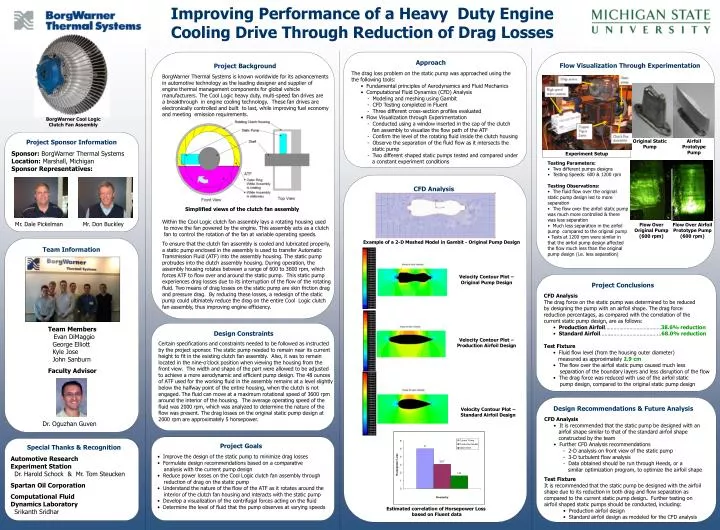
Improving Performance of a Heavy Duty Engine Cooling Drive Through Reduction of Drag Losses Project Background BorgWarner Thermal Systems is known worldwide for its advancements in automotive technology as the leading designer and supplier of engine thermal management components for global vehicle manufacturers. The Cool Logic heavy duty, multi-speed fan drives are a breakthrough in engine cooling technology. These fan drives are electronically controlled and built to last, while improving fuel economy and meeting emission requirements. Simplified views of the clutch fan assembly Within the Cool Logic clutch fan assembly lays a rotating housing used to move the fan powered by the engine. This assembly acts as a clutch fan to control the rotation of the fan at variable operating speeds. To ensure that the clutch fan assembly is cooled and lubricated properly, a static pump enclosed in the assembly is used to transfer Automatic Transmission Fluid (ATF) into the assembly housing. The static pump protrudes into the clutch assembly housing. During operation, the assembly housing rotates between a range of 600 to 3600 rpm, which forces ATF to flow over and around the static pump. This static pump experiences drag losses due to its interruption of the flow of the rotating fluid. Two means of drag losses on the static pump are skin friction drag and pressure drag. By reducing these losses, a redesign of the static pump could ultimately reduce the drag on the entire Cool Logic clutch fan assembly, thus improving engine efficiency. • Approach • The drag loss problem on the static pump was approached using the • the following tools: • Fundamental principles of Aerodynamics and Fluid Mechanics • Computational Fluid Dynamics (CFD) Analysis • - Modeling and meshing using Gambit • - CFD Testing completed in Fluent • - Three different cross-section profiles evaluated • Flow Visualization through Experimentation • - Conducted using a window inserted in the cap of the clutch • fan assembly to visualize the flow path of the ATF • - Confirm the level of the rotating fluid inside the clutch housing • - Observe the separation of the fluid flow as it intersects the • static pump • - Two different shaped static pumps tested and compared under • a constant experiment conditions Flow Visualization Through Experimentation BorgWarner Cool Logic Clutch Fan Assembly Project Sponsor Information Sponsor: BorgWarner Thermal Systems Location: Marshall, Michigan Sponsor Representatives: Mr. Dale Pickelman Mr. Don Buckley Original Static Pump Airfoil Prototype Pump Experiment Setup • Testing Parameters: • Two different pumps designs • Testing Speeds: 600 & 1200 rpm • Testing Observations: • The fluid flow over the original static pump design led to more separation • The flow over the airfoil static pump was much more controlled & there was less separation • Much less separation in the airfoil pump compared to the original pump • Tests at 1200 rpm were similar in that the airfoil pump design affected the flow much less than the original pump design (i.e. less separation) CFD Analysis Flow Over Original Pump (600 rpm) Flow Over Airfoil Prototype Pump (600 rpm) Team Information Team Members Evan DiMaggio George Elliott Kyle Jose John Sanburn Faculty Advisor Dr. Oguzhan Guven Example of a 2-D Meshed Model in Gambit - Original Pump Design Velocity Contour Plot – Original Pump Design • Project Conclusions • CFD Analysis • The drag force on the static pump was determined to be reduced • by designing the pump with an airfoil shape. The drag force • reduction percentages, as compared with the correlation of the • current static pump design, are as follows: • Production Airfoil…………………………………38.6% reduction • Standard Airfoil……..…….……………………...68.0% reduction • Test Fixture • Fluid flow level (from the housing outer diameter) • measured as approximately2.9 cm • The flow over the airfoil static pump caused much less • separation of the boundary layers and less disruption of the flow • The drag force was reduced with use of the airfoil static • pump design, compared to the original static pump design Design Constraints Certain specifications and constraints needed to be followed as instructed by the project sponsor. The static pump needed to remain near its current height to fit in the existing clutch fan assembly. Also, it was to remain located in the nine-o’clock position when viewing the housing from the front view. The width and shape of the part were allowed to be adjusted to achieve a more aerodynamic and efficient pump design. The 48 ounces of ATF used for the working fluid in the assembly remains at a level slightly below the halfway point of the entire housing, when the clutch is not engaged. The fluid can move at a maximum rotational speed of 3600 rpm around the interior of the housing. The average operating speed of the fluid was 2000 rpm, which was analyzed to determine the nature of the flow was present. The drag losses on the original static pump design at 2000 rpm are approximately 5 horsepower. Velocity Contour Plot – Production Airfoil Design • Design Recommendations & Future Analysis • CFD Analysis • It is recommended that the static pump be designed with an • airfoil shape similar to that of the standard airfoil shape • constructed by the team • • Further CFD Analysis recommendations • - 2-D analysis on front view of the static pump • - 3-D turbulent flow analysis • - Data obtained should be run through Heeds, or a • similar optimization program, to optimize the airfoil shape • Test Fixture • It is recommended that the static pump be designed with the airfoil • shape due to its reduction in both drag and flow separation as • compared to the current static pump design. Further testing on • airfoil shaped static pumps should be conducted, including: • Production airfoil design • Standard airfoil design as modeled for the CFD analysis Velocity Contour Plot – Standard Airfoil Design • Project Goals • Improve the design of the static pump to minimize drag losses • Formulate design recommendations based on a comparative • analysis with the current pump design • Reduce power losses on the Cool Logic clutch fan assembly through • reduction of drag on the static pump • Understand the nature of the flow of the ATF as it rotates around the • interior of the clutch fan housing and interacts with the static pump • Develop a visualization of the centrifugal forces acting on the fluid • Determine the level of fluid that the pump observes at varying speeds Special Thanks & Recognition Automotive Research Experiment Station Dr. Harold Schock & Mr. Tom Steucken Spartan Oil Corporation Computational Fluid Dynamics Laboratory Srikanth Sridhar Estimated correlation of Horsepower Loss based on Fluent data