Download
1 / 25
440 likes | 945 Views
Drilling Engineering – PE 311 An Introduction to Drilling Drill Bits. Introduction.

E N D
Drilling Engineering – PE 311 An Introduction to Drilling Drill Bits
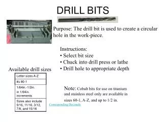
Introduction A drilling bit is the cutting tool which is made up on the end of the drillstring. The bit drills through the rock by scraping, chipping, gouging or grinding the rock at the bottom of the hole. Drilling fluid is circulated through passageways in the bit to remove the drilled cuttings. There are however many variations in the design of drill bits and the bit selected for a particular application will depend on the type of formation to be drilled. The drilling engineer must be aware of these design variations in order to be able to select the most appropriate bit for the formation to be drilled. The engineer must also be aware of the impact of the operating parameters on the performance of the bit.
Classification of Drilling Bits Classification of Drilling Bits
Classification of Drilling Bits Drag Bit Drag bits were the first bits used in rotary drilling, but are no longer in common use. A drag bit consists of rigid steel blades shaped like a fish-tail which rotate as a single unit. The decline in the use of drag bits was due to: The introduction of roller cone bits, which could drill soft formations more efficiently If too much WOB was applied, excessive torque led to bit failure or drill pipe failure Drag bits tend to drill crooked hole, therefore some means of controlling deviation was required
Classification of Drilling Bits Drag Bit
Classification of Drilling Bits Roller Cone Bits
Classification of Drilling Bits Roller Cone Bits This drill bit was invented by Howard Hughes. The roller-cone bit has conical cutters or cones that have spiked teeth around them. As the drilling-string is rotated, the bit cones roll along the bottom of the hole in a circle. New teeth come in contact with the bottom of the hole, crushing, scraping, and gouging the rock immediately below and around the bit tooth. The high-velocity fluid jet strikes the crushed rock chips to remove them from the bottom of the hole. As this occurs, another tooth makes contact with the bottom of the hole and creates new rock chips. Thus, the process of chipping the rock and removing the small rock chips with the fluid jets is continuous.
Classification of Drilling Bits Roller Cone Bits Advantages of roller cone bits are: Improved cleaning action by using jet nozzles Using tungsten carbide for hardfacing and gauge protection Introduction of sealed bearings to prevent the mud causing premature failure due to abrasion and corrosion of the bearings.
Classification of Drilling Bits Roller Cone Bit - Geometry The geometric design features that determine cutting action are the journal angle and the offset. Journal Angle: is the angle formed by the intersection of a line perpendicular to the axis (or center line) of the journal and the center line of the bit. Soft formation bits have smaller journal angles than hard formation bits.
Classification of Drilling Bits Roller Cone Bit - Geometry Offset is the horizontal distance between a vertical plane of the center line of the bit and a vertical plane through the center-line of the journal. This Figure shows this offset as a positive displacement in the direction of rotation (some bit companies measure offset in inches, while others measure it in degrees. Typical bit offsets range from 0° to 5°) The greater a bit's offset, the more scraping is its cutting action.
Classification of Drilling Bits Roller Cone Bit – Cutting Elements The two basic categories of rolling cutter bits are defined by their cutting elements. A bit may either have milled steel teeth or tungsten carbide inserts. Milled steel tooth cutters are an integral part of the bit cone. Soft formation bits have long, relatively thin teeth that are spaced widely apart on the cone This configuration promotes a gouging/scraping action that results in high penetration rates with minimal weight on bit. Unfortunately, these long teeth are especially susceptible to breakage in harder rock.
Classification of Drilling Bits Roller Cone Bit – Cutting Elements Milled steel tooth (cont.) Teeth are positioned on the cone in rows, with the inner rows on each cone meshing with one another. This tooth arrangement provides the optimum design space for a given hole size, promotes self-cleaning of the teeth as the bit turns, and provides maximum hole coverage
Classification of Drilling Bits Roller Cone Bit – Cutting Elements Tungsten carbide inserts, as their name implies, are not part of the cone material. Rather, they are separate elements, pressed into specially machined holes in the cone. They can be placed either as gauge inserts (along the outside of the cone) or inner row inserts.
Classification of Drilling Bits Roller Cone Bit – Cutting Elements
Classification of Drilling Bits Diamond Bits Diamond has been used as a material for cutting rock for many years. The hardness and wear resistance of diamond made it an obvious material to be used for a drilling bit. The diamond bit is really a type of drag bit. A new generation of diamond bits known as polycrystalline diamond compact (PDC) bits were introduced in the 1980’s. PDC bits have been run very successfully in many areas around the world.
Classification of Drilling Bits Diamond Bits - PDC The PDC drill bits were introduced to the drilling industry in 1967. A PDC cutter consists of a stud covered by an artificial diamond layer bonded in a high pressure/high temperature sintering process.
Classification of Drilling Bits Diamond Bits - PDC The ability of the PDC bits to drill different formations with excellent efficiency was proven to the industry (Millheim, 1986). The main advantages of the PDC bits are: Longer life (Better wear resistance) Higher average ROP Better drilling economics ( $/m)
Classification of Drilling Bits Classification - Roller Cone Bits The IADC categorizes for rolling cutter bits using a four-character code: 517X The first character in the classification code indicates the cutting structure series. The digits 1 - 3 are for steel tooth bits in the soft, medium and hard formation categories The numbers 4 - 8 are for insert bits in the soft, medium, medium hard, hard and extremely hard formation categories.
Classification of Drilling Bits Classification - Roller Cone Bits The second character further specifies the cutting structure type within each series classification: 517X The third character indicates bearing type and whether or not the bit is gauge-protected. The fourth character designates additional special features and applications:
Classification of Drilling Bits Classification - Roller Cone Bits Example: A Smith F2 bit has an IADC classification of 517X: 51 indicates that the Smith F2 has tungsten carbide inserts, designed for use in soft formations with low compressive strength; 7 indicates that the cones on this bit have sealed friction bearings, and that the bit is designed for protection against gauge wear; X indicates that the inserts have a chisel tooth configuration (as opposed, for example, to a conical shape).
Classification of Drilling Bits Classification – Fixed Cutter Bits The IADC also categorizes for fixed cutter bits using a four-character code: M431 The first character indicates the type of body material and cutting elements: M431 S for steel body PDC bits; M for matrix body PDC bits; D for natural diamond bits; T for TSP bits (Thermal Stable Polycrystalline: Natural diamond). The next three numbers indicate the following: Formation Type To Be Drilled: M431 Cutting Structure: M431 Bit Profile: M431
Geological formation type to be drilled are classified in the following manner: M431 1 or 2: Soft and soft sticky-Highly drillable formations such as clay, marl, gumbo and unconsolidated sands. 3: Soft-medium-Low compressive strength sands, shales and anhydrites with hard layers intermixed. 4: Medium-Moderate compressive strength sand, chalk, anhydrite and shale. 6: Medium hard-Higher compressive strength with non or semi-sharp sand, shale, lime and anhydrite. 7: Hard-High compressive strength with sharp layers of sand or siltstone. 8: Extremely hard-Dense and sharp formations such as quartzite and volcanic rock. Classification of Drilling Bits Classification – Fixed Cutter Bits
PDC cutting structure is denoted in the following way: M431 2 - This bit has mostly 19mm cutters 3 - This bit has mostly 13 mm cutters 4 - This bit has mostly 8 mm cutters Classification of Drilling Bits Classification – Fixed Cutter Bits
Bit profile: M431 1 - Short Fishtail 2 - Short Profile 3 - Medium Profile 4 - Long Profile Classification of Drilling Bits
For example: M431 M – Matrix body PDC bit 4: This bit will perform well in medium formations. 3: Cutting Structure consists of primarily 13 mm PDC cutters.1: Short fishtail bit profile For example: M612 M = Matrix body PDC bit 6 - This bit will perform well in Medium hard-Higher compressive strength1 - Cutting Structure consists of natural diamond,2 - Short Profile Classification of Drilling Bits